Spintires: MudRunner Map Modding Guide / How to make MudRunner Map
This guide documents every feature of the MudRunner map editor, plus how to create custom objects for your map. You can read (or skim) sequentially through the guide to learn everything there is to know, or you can use it as a reference when you want to learn more about a particular feature.
What I put in this guide that I can’t find elsewhere:
- Easy reference material for all Russian trucks, trailers, addons, and their permitted combinations.
- Bugs in the game that you want to avoid in your custom map.
- Information about all editable map properties.
- How to create and use reference maps.
- How to create custom materials, distribution brushes, roads, dynamic models, and even plants.
- Tips for using Blender with MudRunner.
- And more!
Introduction
*** Uninstalling the MudRunner Editor will erase all of your files! ***
Be sure to read the “Directory Structure and Archives” section to avoid a catastrophe.
This guide is organized in four major parts.
The first half of the guide describes how to use every feature of the map editor. Experienced map makers won’t need to read this part, but I bet even experts can learn a few things from it.
The remaining information is grouped into three appendices.
Appendix A groups together all the reference information you need while making a map. Once you’ve read the rest of the guide, this is the part you’re most likely to return to while working on your map. Experienced map makers can figure out most of this material as they need it, but all map makers will be happy to have it all summarized in one place for easy reference. The reference information also includes a list of game bugs that might affect your custom map, especially ones that are easy to miss until after you’ve published.
Appendix B describes how to edit your map files by hand. You can’t do much by hand that you can’t do with the editor, but you may be able to perform some tasks outside the editor more quickly or easily than you can in the editor.
Appendix C describes how to create custom features for your map. Topics covered so far:
- Custom river colors.
- Custom materials.
- Custom distribution brushes.
- Custom road overlays and overlay brushes.
- Custom static, dynamic, and breakable models, including lights.
- Custom grass.
- Custom plants.
Topics I hope to add soon:
- Information about multiplayer.
- Summaries of trucks in American Wilds.
Topics I don’t plan to add:
- Importing from the original Spintires editor.
- Custom trucks. (Trucks have their own specialized guides.)
- Custom particle effects, sky illumination, and other game-wide effects.
Initialize the MudRunner Editor
Install the Editor
If you own MudRunner on Steam, the editor is free, but it’s a bit hard to find. In the Steam window, hover your mouse over “LIBRARY” until the menu pops up. Then click on “TOOLS”.
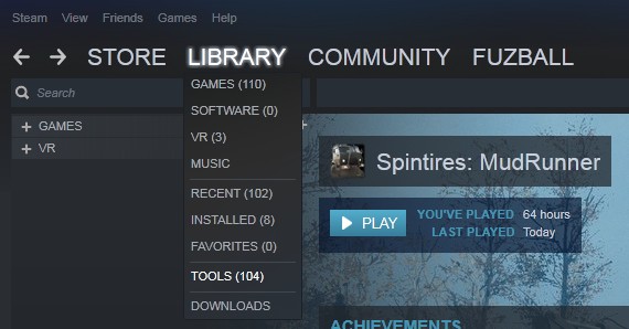
In the list of tools, select “Spintires: Mudrunner – Editor” and install it. Make sure to create a desktop shortcut for easy access.
Editor Settings
Before the editor can do anything useful, it needs to have access to the MudRunner media files. Run the editor and select Settings⇒Paths from the top menu.
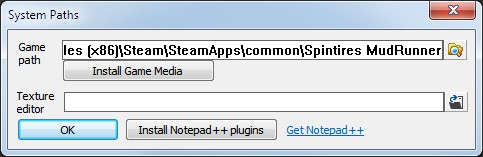
Type in or navigate to the Steam directory of the MudRunner application. It is likely to be something like this:
C:\Program Files (x86)\Steam\SteamApps\common\Spintires MudRunner
Then click “Install Game Media”. This will unpack and install all of the game assets into the Editor’s application directory. After any major game updates or DLC releases, you can click “Install Game Media” again to pick up the changes.
Except for the new USA trucks, the assets for all DLC and expansions are available to modders. So you can safely assume (for now) that any non-truck asset available to you is also available to everyone who downloads your map.
The settings dialog also has a line to input the path to your texture editor. You can enter the path to your favorite texture or bitmap editor here. I don’t find this useful, so I just leave it blank.
The “Install Notepad++ plugins” button is a bit wonky, and the plugins aren’t very useful for map editing, so I recommend that you skip that. You might want to click the “Get Notepad++” link if you plan to edit any XML by hand. It’s a decent, quick editor.
Once you’re done, click “OK” to return to the main editor window.
Initialize a Map
Create a New Mod
The editor assumes that you are creating a level with the intention of publishing it to the Steam Workshop. Thus, to create a level you must first create a workshop item (a mod).
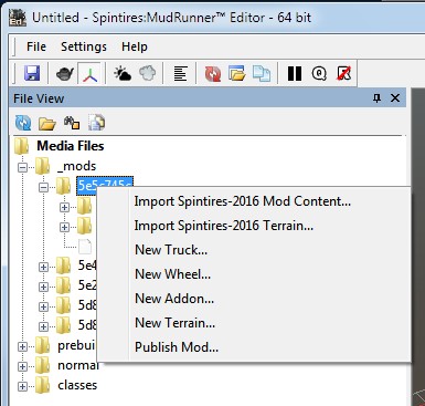
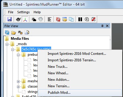
In the left panel, “File View”, under “Media Files”, right click on “_mods” and select “Create New Mod”.
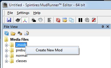
You might not see an obvious effect if the _mods directory is closed. Open it up by clicking the “+” next to _mods, or double-click _mods. There you will find a new directory with a random hexadecimal name. You can also open that to look inside. The editor has already created directories for trucks and wheels, but we won’t use those for map editing.
Note that all of these directories are under the MudRunner Editor application directory. If you uninstall the editor, they may get deleted. Keep backups!
At this point, you can navigate the web to the Steam Workshop and see the empty new “Spintires: MudRunner” item among your own creations. This will remain empty until you eventually publish your map.
This guide won’t talk much about using the Steam Workshop tools. I generally find the Steam website to be fairly intuitive and easy to navigate without additional documentation.
Create a New Map
Now right click on the mod directory (the hexadecimal number) and select “New Terrain…”
A dialog box allows you to name the level and choose its size.
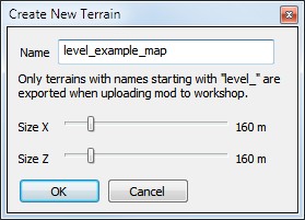
As the dialog warns, the level name must start with “level_”, or you won’t be able to publish it. (It’ll work just fine in the editor and the proving grounds, however.) This level name is only for your own use. You’ll get to pick a better name when you publish your map to the Workshop.
The official documentation recommends that you use only lowercase letters, numbers, and the underscore (“_”) in the level name. I recommend that you stick to their recommendation.
The dialog also allows you to choose the map dimensions in the X (east-west) and Z (north-south) directions. These dimensions are measured in meters, and each dimension must be a multiple of 32 meters. The “no entry” barrier in the game prevents trucks from getting about 12 meters from the edge of the map, so the minimum 32m x 32m size isn’t large enough to be useful for anything. Choose a larger size.
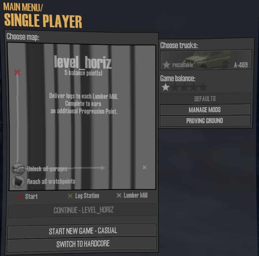
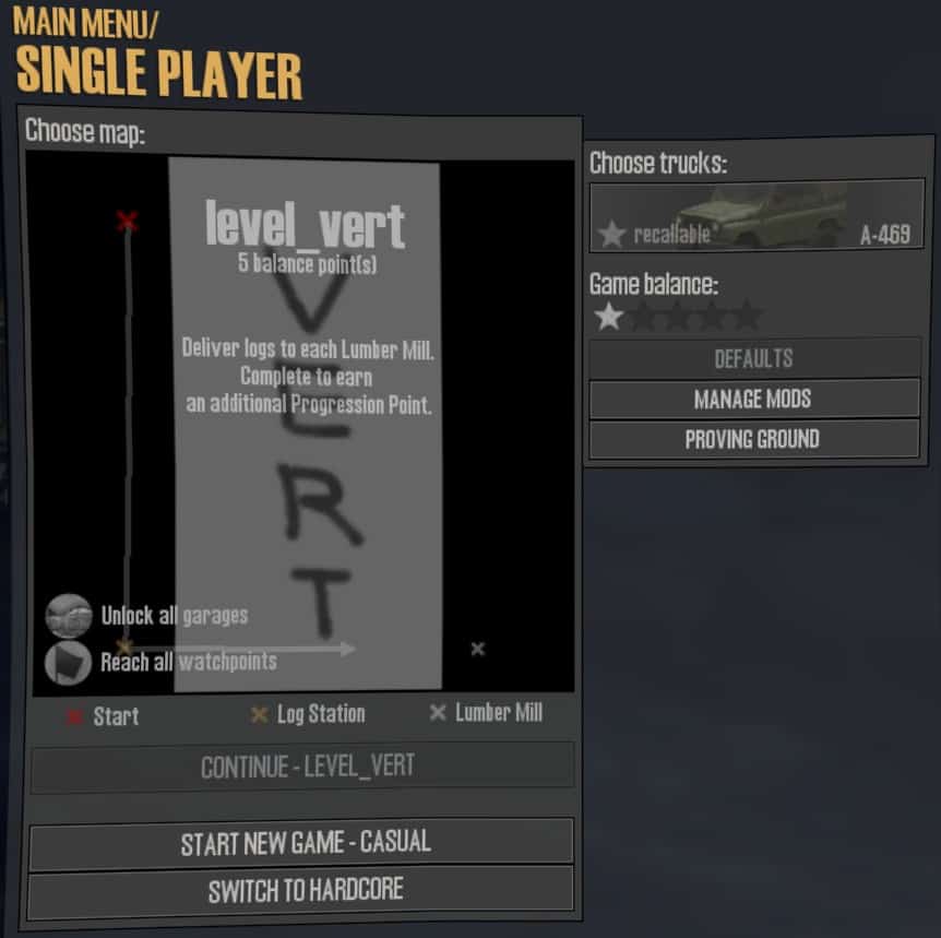
I recommend that your map be square. A rectangular map will work fine in the editor and proving grounds, but when players download the published map and try to select it in the game, the preview map will display incorrectly. A horizontal rectangle will display only vertical stripes. A vertical rectangle will display mostly correctly, but the overlays showing the starting location and the lumber stations and lumber mills will be incorrectly stretched over the map.
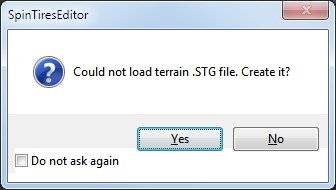
When you click “OK” in the dialog, you will get a new dialog asking to create the .STG file. Click “Yes” on that. I’ll describe the purpose of the STG file later in the guide.
Multiple Maps in One Mod
You can select “New Terrain…” multiple times for the same mod, and all of the maps will be packaged together in the same mod. This is useful if you want to publish related maps as a set.
Import a Map from Spintires
If you created a map for the original Spintires, the MudRunner Editor can import it and convert it to MudRunner format. Right click the mod directory and select “Import Spintires-2016 Terrain…”
Unfortunately, I lost most of my original Spintires fires, so I cannot tell you much about how this works. My impression is that it will do fairly well with most of the map features. Road overlays and rivers may change shape somewhat, so they will need to be reviewed. Some models have changed name, changed size, or been removed from the game, so you will probably have to correct a few of them.
Be aware that the boundaries at the edge of the map have been moved a bit closer to the center of the map. So if you have any paths near the edge, they may need to also be moved to avoid any problems.
The Top-level Prebuild Directory
You can also choose “New Terrain…” from the top-level prebuild directory (Media/prebuild). This lets you experiment with maps without first creating a Steam mod. It comes with disadvantages, though:
- Your files are mixed in with the built-in files.
- You’ll need to update the game’s Config.xml to point to the editor’s Media directory. (See “Shortcut Past the Proving Ground” in the “Test Your Map” section.)
- When you’re ready to create a mod and publish, you’ll need to manually copy your files to the new mod directory.
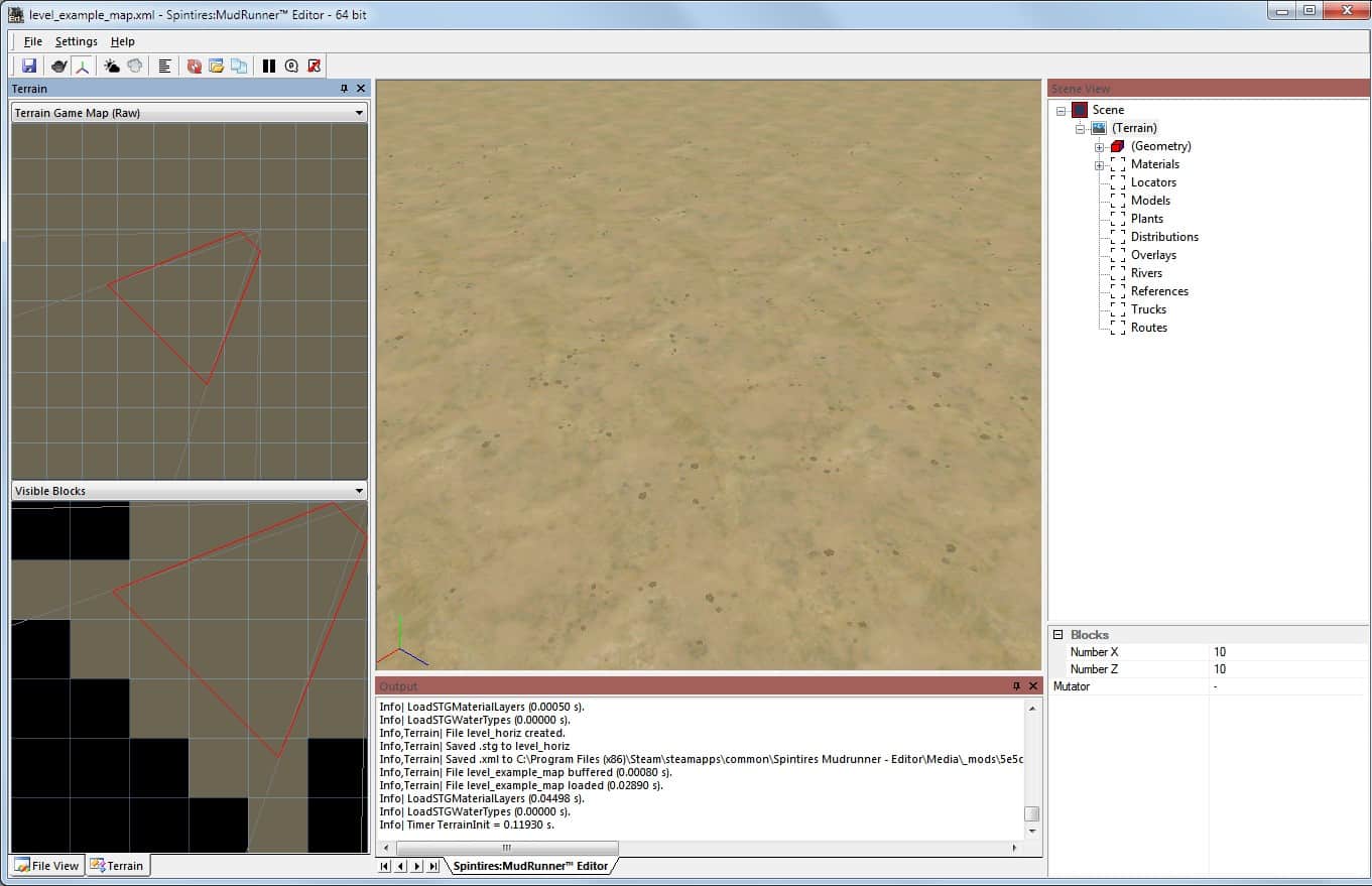
Introduction to the Map Editor Views
After creating a new map, the map editor opens. It contains a number of sections that I’ll go over briefly here.
Menu Bar
The menu bar at the top of the window has File, Settings, and Help menus.
The File menu lets you close or save the current map, open a recently edited map or other file, or exit the editor. You will use the “Save” function a lot of course; its keyboard shortcut is ctrl-S. The MudRunner Editor will occasionally overwhelm the display engine and hang before eventually crashing. My experience is that in many cases the editor is still accepting input while the display engine is hung, so you can still save with ctrl-S before it crashes.
You’ve already seen the Settings menu.
The Help menu opens the official editor guide in a new PDF window. The official PDF has a short section on map editing at the end, but it’s barely enough to get you started. Warning: Steam treats the running PDF viewer as part of the MudRunner Editor application. If you quit the editor and try to restart it while the PDF viewer is still running, Steam will complain that the editor is “already running”. Kill the PDF viewer to allow the editor to restart.
Toolbar
Under the menu bar is a toolbar with a row of icons for various features. You can hover over most icons to get a description of what they do. Night mode, Duplicate selected, and Local transform are occasionally useful. Night mode is easily understood. Duplicate is documented in The Context Menu section. Local Transform is documented in the Move a Truck, Model, or Plant section. Save is also useful, of course, but I always use the secret keybinding, ctrl-S.
Main View
Most of your time will be spent in the main view. This view is unlabeled, but you can find it centered between the Terrain view on the left and the Scene View on the right. It initially shows a blank patch of dirt in the center of your map.
Navigating within the main view is covered in its own section of this guide.
Output View
The Output view at the bottom shows logging information and error messages from the game engine. You will refer to it occasionally when things go wrong.
Note that the Output view will often contains lines saying “D3D9Device lost” and “D3D9 Device reset”. These messages look ominous, but they seem to be part of normal operation, and you can ignore them.
At the bottom of the Output view are four arrows pointing left and right. I do not know what these do.
The angled tab at the bottom of the Output view indicates that it is showing the main log from the Spintires:MudRunner Editor. On occasion, another tool within the editor may create a separate tab in the Output view in order to display its log. You can then click on the angled tabs to switch between logs.
Terrain View
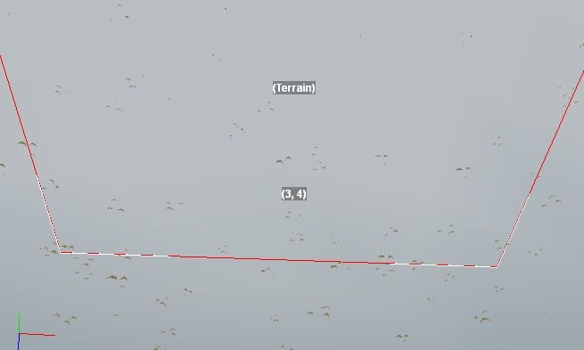
The Terrain view on the left includes two panels looking into the scene from a top-down view.
By default, the upper panel shows a view of the entire map. A truncated triangle shows the field of view of the camera in the main view to the right.
A dropdown menu above the upper panel changes it to show many other map textures used by the game engine. I don’t find these to be very useful. Once you’re done looking around, flip it back to the default “Terrain Game Map (Raw)” at the end of the dropdown list.
You can left click in the upper panel to select a terrain block, or double left click to fly the camera to that block. You can also hold the “control” key while you left click to add or remove a terrain block from the current selection.
By default, the lower panel is similar to the top one, but it zooms in on the terrain blocks that are visible to the camera. (I’ll describe terrain blocks later in the guide.) A truncated triangle again shows the field of view of the main view’s camera. Only those terrain blocks within this view (or very near it) are drawn in the lower panel.
Another dropdown menu allows the lower panel to be switched to show only the “Selected Blocks”.
I find the “Visible Blocks” default to be the more useful view for the lower panel.
File View
At the bottom of the Terrain view are two tabs which you can use to switch between File View and Terrain view. More information about arranging views, panes, and tabs can be found in the next section.
Click the “File View” tab to return to the view of the various media files, including your mod directory. This view should show you the “prebuild” directory containing the XML file for your new map. However, the editor didn’t update its file list after creating the new level. To see the new directories and files, click the icon with circling arrows just below the File View titlebar.
From here you can double-click any map’s XML file in its prebuild directory to open that map. Only one map can be open at a time, so if you have a map open already, the editor will prompt you to save it before opening a new one.
Remember that you can open a recently edited map by selecting it from the File menu, but you can open any map at all by double clicking its XML file under the prebuild directory for its mod.
Note that all of these directories are under the MudRunner Editor application directory. If you uninstall the editor, they may get deleted. Keep backups!
The remaining icons under the File View titlebar are as follows.
The folder icon opens the currently selected directory in a Windows Explorer window. This is handy if you want to edit files by hand, delete unnecessary files, or perform other operations.
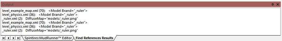
The binoculars icon finds all references to the selected file. For example, it can find all maps that use a reference map, or it can find all references to a custom asset. Confusingly, clicking the binoculars icon appears to toggle it on or off, but it’s really just a button; click it to find references. The list of references is displayed in the Output view a new tab called “Find References Results”.
The fourth icon has the hover text “Show All Files”. By default, various uninteresting directories are hidden in the File View. Click this icon to display them, or click it again to hide them. A description of the various files and directories (including hidden ones) is in the next section of this guide.
Scene View
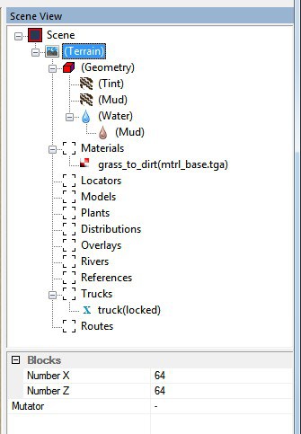
The Scene View on the right contains a categorized list of all the features on the map.
Unlike the File View, double clicking will not expand or collapse a portion of the list. You must click on the “+” or “-” icons to expand or collapse an item.
The “(Geometry)” category always has a standard set of features within it. For a new map, the “Materials” category has one material in it, and all the other categories are empty. As you add features to your map, you will add items within the Materials category and to the other categories. Each of these scene categories will be discussed in detail later in this guide.
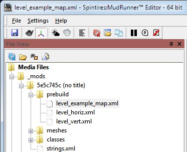
Directory Structure and Archives
It is useful to understand the directory structure used by the MudRunner Editor since you will need to occasionally interact with it. In the below screenshot, I’ve switched the editor to “Show All Files” and refreshed the file list to show all the files created while the map was initialized.
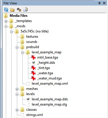
Under the _mods directory is your mod directory with a gibberish hexadecimal name. Under that are all the files and directories for your mod.
The textures, sounds, meshes, and classes directories are initialized by the editor because they are often useful when modding a truck. However, they start out empty, and you will only use them if you create custom assets for your map.
Also under your mod directory is a strings.xml file. When it’s time to publish your mod, you’ll edit this file to give your map(s) a proper name.
All of the most interesting files for map editing are in the “prebuild” directory. This directory includes your map’s XML file (e.g. level_example_map.xml) and a bitmap directory (e.g. level_example_map). The directory contains a few bitmap files in TGA and DDS format and the mud file. You will likely add many more bitmap files during the course of creating your map.
The files in the prebuild directory are only used by the MudRunner Editor and not by the game. Think of them as the source files for your map. The “levels” directory contains the files used by the game itself. Think of these as the “compiled files”. For each map, the levels directory has a DDS file (which contains all of the bitmaps/textures needed by the game engine) and an STG file (which contains everything else the game engine needs to know).
For each change you make while editing your map, the editor updates the data for the prebuild files and also updates the data for the game engine. In fact, the MudRunner Editor uses the same engine to display the map in progress as the MudRunner game uses to play the map. This is why when you opened the level for the first time, the editor immediately asked to create the STG (and associated DDS) data.
The above paragraph talks about updating the “data” rather than the files. As you edit your map, the editor automatically updates the TGA and DDS files in the prebuild directory. However, the data assocated with your map’s XML file and with the levels directory is kept in internal memory.
Pressing ctrl-S (save) writes the XML file back to the prebuild directory and writes the STG and DDS files to the levels directory.
If the compiled data ever gets out of sync with the prebuild data, you’ll see the wrong terrain in the editor’s main view. To fix this, right click in the main view and select “Rebuild Terrain”. This sometimes happens because the editor tries to save time by performing only limited recompilation. It can also happen if you edit any files outside the editor, so you need to manually tell the editor to recompile.
Create Archives
The MudRunner Editor does not save your files to the Steam Cloud. Even worse, if you ever uninstall the MudRunner Editor tool, it erases everything in its application directory, including all your files! Even if you avoid that, there is always the danger for a file to get corrupted through no fault of your own. For that reason, keeping archives of your work is important.
The easiest archival method is to occasionally copy the necessary directories to another folder. At the least, copy it to somewhere not in the MudRunner Editor application directory. Even better, copy it to a different drive in case you have a drive failure.
If you don’t have any custom assets, you can simply copy the “prebuild” directory from your mod directory. If you do have custom assets, you’ll want to copy the entire mod directory. You can then delete the “levels” directory from the copy if you want to save space.
Recreate your Mod Directories
Whenever you run the MudRunner Editor, it connects to Steam to find out what mods you control. If you own a mod, but the directory is missing, the editor will recreate it. This is useful if you’ve reinstalled the MudRunner Editor or if you’ve installed it on another computer. Copy your archived files into the recreated directory, and you’re ready to go again.
Delete a Mod
If you delete a mod from the Steam Workshop website, you will no longer be able to publish to that mod, but your files will remain untouched on your drive. (At least, that’s what happened when I tested it. You still probably want to make an archive copy first, just in case.)
If you want to continue the map in a fresh mod, you can create a new mod and copy your files to the new mod directory.
Navigate in the Main View
The main view shows the 3-D map from the perspective of a virtual camera. To view different parts of the map, the camera can be moved in all three dimensions, it can be panned left and right, and it can be tilted up and down. To prevent disorientation, the camera is never tilted left or right.
A small icon in the lower left of the main view shows the coordinate axes as they appear from the current camera angle. The red line shows the X axis and always points east. The green line shows the Y axis and points up. The blue line shows the Z axis and points north. The MudRunner coordinate system is described in more detail in a later section.
You can move the camera around as follows:
- left click and drag* – move the camera around whatever terrain you clicked on and rotate the camera to continue pointing at that spot. This is my favorite method for rotating the camera.
- mouse wheel up or down – push the camera closer to the terrain under the mouse or pull it further away. (Caveat: the most recent click or drag must have been in the main view.)
- ctrl + left click and drag* – keep the camera pointed the same way while moving it relative to whatever terrain you clicked on. This effectively drags the terrain around under the mouse, and it’s my favorite method for moving the camera across the map.
- shift + left click and drag – keep the camera fixed in space and rotate it to point in new directions.
- alt + left click and drag – move the camera around the already selected object and rotate the camera to keep that object in the same spot in the view (or off view).
Other controls in the main view:
- left click* – select the terrain block or object under the mouse.
- double left click* – same as left click, and also jump the camera to a close view of the selected item.
- right click – bring up a context menu. This will be covered later in the guide.
(*) You can’t click on terrain that is more than ~400 meters from the camera. Left click and double left click do nothing. Left click and drag behaves as shift + left click and drag. Ctrl + left click and drag moves the camera extremely slowly.
It is very easy to get completely lost in the main view so that no terrain is visible. If the camera is too far away from it, the game engine won’t draw it. If that happens, double click in the Terrain view to recenter your camera over the terrain.
If the camera is below the terrain, the game engine also won’t draw it. In that case, double clicking in the Terrain view will move the camera close to the terrain, but still pointing up at it, so the terrain is not drawn. In that case, left click and drag downwards to tilt the camera downward while moving the camera itself upward until the terrain comes into view.
Create a Truck, Model, or Plant
The minimum requirement to publish a map is that it has a starting truck, so we’ll begin with that. Trucks are part of a collection of map features which I call “objects”. These include trucks, models, plants, and locators. Locators are different enough to be described separately. This section of the guide describes how to create a truck, model, or plant.
Create a Truck
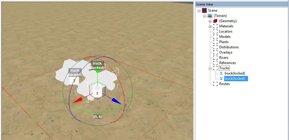
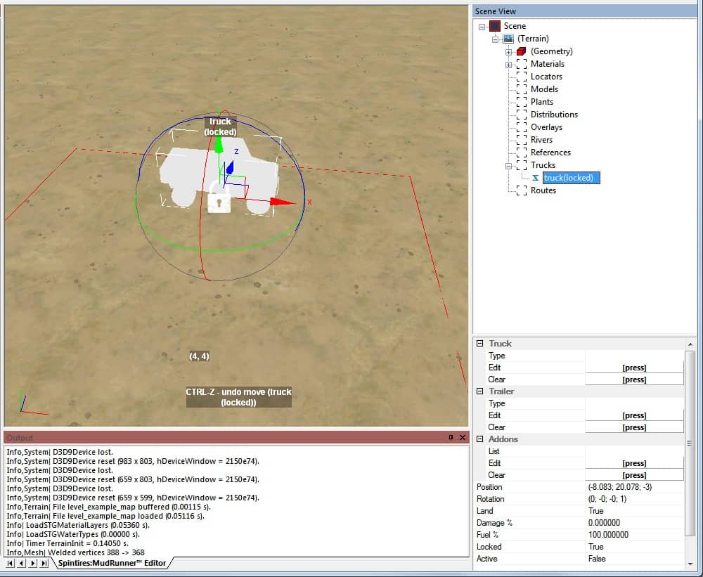
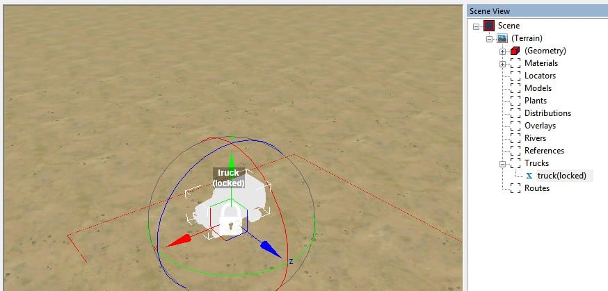
Right click anywhere in the main view and select “Add Truck”. A generic white truck will appear in the middle of the view (regardless of where you clicked).
The new truck comes with some new interface elements. If these are all jumbled together, zoom in until you can distinguish the individual elements.
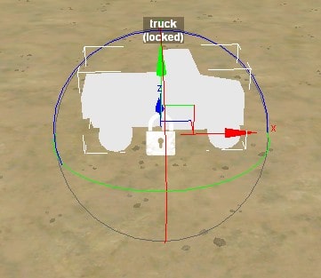
The text above the truck indicates its type, which for now is just a generic “truck”. The text also indicates that the truck is locked. The white padlock over the truck indicates the same thing. Locked trucks and all other truck details are discussed in the next section. Here, we’ll concentrate on features common to many kinds of objects.
The colored interface elements allow you to move and rotate the truck. These manipulations are described in the next section.
When a truck is created, it is automatically selected for editing. Unfortunately, you cannot click on a truck in the main view to select it. You can only select it by left clicking it in the Scene View.
Create a Model or Plant
Right click anywhere in the main view and select “Add Model” or “Add Plant”. A window appears where you can select what model or plant you wish to create. Left click to make your choice and click “OK” or press the enter key. Or double-click an item to choose it and immediately confirm your choice. The selected object will appear in the middle of the view (regardless of where you clicked).
Conveniently, you do not need to own a DLC or expansion in order to use models or plants from that DLC or expansion. Nor does a player need to own the DLC or expansion as long as her game is up to date. (The situation is different for trucks, however.)
Unlike a truck, you can left click on a model or plant in the main view to select it.
Introduction to Feature Properties
Now is a good time to describe some standard interface conventions in the MudRunner Editor.
Types of Features
This guide groups features into three types:
- A truck, locator, model, plant, or reference is a simple object. It has a single location and orientation.
- An overlay, river, or route is a spline object. It has a number of points, each with a position but not an orientation.
- Everything else is just a feature, not an object. This includes geometry features, materials, and distributions.
Simple objects and spline objects are together referred to simply as objects.
Select a Feature
You can select a feature to edit by left clicking the feature in the Scene View.
You can also select certain features in the main view:
- Select a model or plant by left clicking the object in the main view.
- Select a spline object by left clicking one of its points in the main view. (However, this doesn’t work for points outside the map boundaries.)
Other objects cannot be selected in the main view. This includes trucks, locators, and references.
Feature Properties
Features may have named properties and/or bitmap properties.
A named property has a name and a value, and it is displayed in the properties panel at the bottom of the Scene View. Named properties are recorded in your map’s XML file in the prebuild directory.
A bitmap property is painted into a bitmap in the main view. Each pixel in the bitmap corresponds to a local region of the map and is displayed in the corresponding section of the main view (which itself has many pixels on the screen). Each bitmap is recorded in a file in your map’s bitmap directory (inside the prebuild directory). The name of the bitmap file is implicit for some features, and it is a named property for other features.
Unless otherwise stated, references to “properties” in this guide refer to named properties.
Edit Named Properties
Most named properties can be edited directly in the properties panel, either by directly typing a new value or by some other means of selecting a new value.
When a property is edited, a ghost abstraction of the feature is drawn in the main view showing the new property values. The changed values are also displayed with bold text in the properties panel. The new property values are not committed and the feature itself is not redrawn until it is deselected.
To deselect a feature and commit its property changes, left click on any other feature in the Scene View. If it is an object, you can also left click anywhere in the main view that is not a manipulable interface for that object. If it is not an object, left click anywhere in the main view. You can also deselect a feature by adding a new feature from the context menu, which automatically selects the new feature. Finally, you can deselect a feature by ctrl-clicking it in the Scene View.
A simple object’s position, orientation, and scale properties can also be modified by manipulating the object’s interface in the main view. This similarly manipulates a ghost abstraction of the object. However, the new property values are not reflected in the property panel until the object is deselected. (This may be an editor bug.) Deselecting the object also commits the property changes and redraws the object. You must then reselect the object to see its new values in the property panel.
A spline object’s points can be moved in the main view. This manipulates a ghost abstraction of the object. The editor also updates the selected point’s properties in the property panel in real time. However, the new property values are not committed and the object itself is not redrawn until it is deselected
If you save your map (ctrl-S) while property changes are not yet committed, those changes are not saved. You might want to get into the habit of always left clicking in the main view before saving.
If you select Rebuild Terrain from the context menu while property changes are not yet committed, those property changes are discarded and all features are deselected. I do not know a faster method to discard all property changes, although the undo function (described later) can undo certain changes.
Rebuild Selection and Rebuild Visible do not deselect the feature or affect its properties.
When selecting named properties, the tab key switches from the left column to the right column, and the enter key returns to the left column. Pressing the up or down arrow keys while in the left column moves the select through the property list.
A few named properties cannot be edited once the feature is created (e.g. the map size). For the editable properties, the editing conventions are different depending on the property type. Editing methods for each property type are described below.
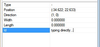
Type Directly
For some properties, you can directly type a new value. Click in either the left column (name) or right column (value) of the desired property in the property panel and begin typing. If you clicked in the left column, your new text entirely replaces the old value. If you clicked in the right column, your new text is inserted where you clicked, and you can generally edit the old or new text. Pressing tab or enter or left clicking somewhere else completes the data entry.
Many named properties will look like they have a value that you can type directly, but when you click the property some other interface pops up. These other interfaces are described below.
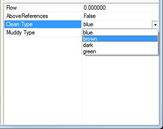
Dropdown Menu
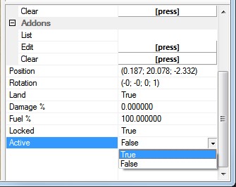
For a property with a dropdown menu, a small downward-pointing arrow appears when you select the property. Click the arrow to get a menu of values that you can choose among. Properties that can be either True or False are the most common use of the dropdown menu.
When the property is selected, you can also type the first letter of the desired value to immediately select that value. If there are multiple values that start with the same letter, typing the letter cycles among those values.
Finally, you can double-click the property to cycle among the values. This is particularly handy for switching between True and False. You have to select the property before you double click in the right column. You can double-click the left column without selecting the property first.
Slider
For a property with a defined range of numerical values, clicking in the right column of the property causes a slider to appear to the right of the property value. The slider can be manipulated using the mouse or keyboard:
- Drag the slider indicator to the right or left to quickly increase or decrease the value.
- Click on the slider to the right or left of the indicator to increase or decrease the value by a large step.
- Press the right or left arrow key on your keyboard to increase or decrease the value by a small step.
- Press the “Home” key on your keyboard to set the value to the minimum value.
- Press the “End” key on your keyboard to set the value to the maximum value.
There is no way to type a value directly into a slider property.

Select Asset
For properties that chose among things that can be represented visually, the editor uses a Select Asset window.
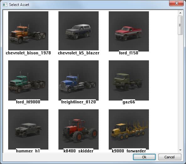
For many objects, the Select Asset window pops up when the object is created in order to choose its type. For other objects, an asset can be selected at any time. For these, the editor displays the name of the current asset as an uneditable value, but it adds a second pseudo-property that allows you to edit the asset property. The value for the pseudo-property displays as “[press]”. Left click the “[press]” text to open the Select Asset window. (The text acts like a button, even though it doesn’t look like one.)
To select an asset, left click it in the Select Asset window and then click “OK” or press enter. Or double-click a truck to choose it and immediately confirm your choice.
Click “Cancel” or press the escape key to cancel the asset selection. If the Select Asset window was opened during the creation of a new object, the object creation is canceled. If you click “OK” or press enter when no asset is selected, it is the same as clicking “Cancel”.
Select Brushes
The appearance of some features depends on which brushes are attached to the feature. Zero, one, or many brushes can be selected using the Select Brush window. The editor displays the names of the current brushes as an uneditable value, but it adds a second pseudo-property that allows you to edit the brush selection. The value for the pseudo-property displays as “[press]”. Pressing the “[press]” text opens the brush selection window.
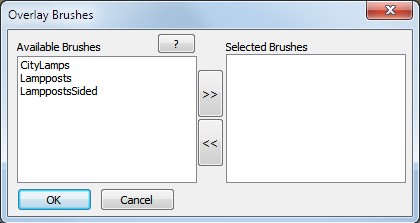
Move a brush from the left “Available Brushes” column to the right “Selected Brushes” column by clicking its name and then the “>>” button. Move it back by selecting it from the right column and clicking “<<“. Or quickly change a brush from one side to the other by double clicking it in either column.
When you are done, click “OK” or press enter to confirm your selection of brushes. Or click “Cancel” or press the escape key to cancel your changes.
The Context Menu
The MudRunner Editor has a context menu that can be invoked by right clicking in a couple of different places. The context menu always includes a number of common entries, and more entries are added for the context of the chosen feature.
In most cases, if you right click anywhere in the main view, the context menu appears for the currently selected feature. However, if a feature with a bitmap property is selected, right click in the main view has a different function. If no feature or terrain block is selected, right click in the main menu does nothing. Generally the only time that nothing is selected is after a feature is deleted or after Rebuild Terrain.
If instead you right click on a feature in the Scene View, the context menu appears for that feature. Note that feature is not actually selected until something is chosen from the context menu (which may or may not select the right-clicked feature).
The rest of this section describes the common context menu entries, plus a few entries that are used by a number of features.
Reload
Reload discards all unsaved changes and reloads the map from disk.
Be very careful with this entry. The editor does not ask for confirmation before reloading. You save your work often, right?
Rebuild Terrain
Rebuild Terrain redraws everything in the map. For a large, complex map, this can take a very long time.
If the editor has taken shortcuts in its iterative drawing (such as not redrawing shadows), Rebuild Terrain will correct the view. It also occasionally reshapes some features such as terrain height and rivers that need a wider context to correctly join together.
Rebuild Terrain discards any property edits in progress that have not been committed, and it clears the current selection.
Rebuild Selection
Rebuild Selection redraws everything in the selected terrain blocks. This takes some shortcuts, but not as many as the editor takes in its iterative drawing. I find it to be not very useful.
If the context menu was opened from the scene view, Rebuild Selection selects the feature that was right clicked on.
Rebuild Visible
Rebuild Visible redraws all visible terrain blocks. This takes some shortcuts, but not as many as the editor takes in its iterative drawing. This is occasionally useful for updating the view of certain features, although I can never remember what. I’ll sometimes try it, and then only choose the slow Rebuild Terrain option if necessary.
If the context menu was opened from the scene view, Rebuild Visible selects the feature that was right clicked on.
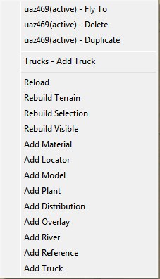
Add < Feature >
This menu item adds the named feature to the map and selects it.
If a map feature is selected, the feature’s category will often add a context menu item such as “Trucks – Add Truck”. This is the same as the generic “Add Truck” menu item, but is a little closer to the mouse when the context menu is invoked.
< Object > – Fly To
Fly To zooms the camera to point at the chosen object and selects it. You can also double click an object in the main view or Scene View to select and fly to it.
If a terrain block is selected, “Fly To” appears at the bottom of the context menu and zooms the camera to point at the terrain block. “Fly To” sometimes also appears in the context menu for a non-object feature, but that also flies to the most recently selected terrain block.
< Feature > – Delete
Delete deletes the chosen object and clears the current selection. This cannot be undone.
< Object > – Duplicate
Duplicate makes a copy of a simple object and selects the copy. This copies all of object’s properties to the new object and selects it. The object can also be duplicated with a shortcut key, ctrl-D.
Note that if the object has some edited properties that have not yet been committed, the new object copies the old values, and then the original object gets the new values as its copy is selected. This can be either useful or surprising, depending on what you were expecting.
If you create an object and duplicate it before committing its property values (by deselecting it), some values may have unexpected values. I notice this particularly with plants, which get duplicated with the “Do Land” property as “false” instead of the normal “true” default.
Move a Truck, Model, or Plant
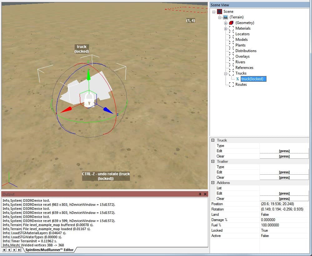
Manipulate an Object in the Main View
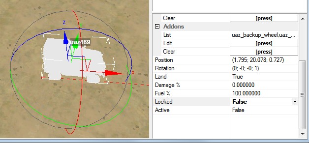
When an object is selected, the main view draws on the object a set of colored arrows corresponding to the X/Y/Z coordinate axes. Left click and drag an arrow to move the object back and forth along that axis. By default, a truck or plant is attached to the ground and cannot be raised into the air, so dragging the green Y arrow does nothing. A model can always be raised or lowered freely.
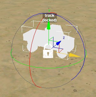
Connecting the bases of the arrows are three squares in 3-D space that designate the XZ plane (ground plane), XY plane, and YZ plane. Dragging one of these squares moves the object around in the 2-D space associated with the plane. The squares will often partially overlap on the screen, which can make it difficult to grab the right one. However, moving in the ground plane is the most generally useful, and the editor always prioritizes that one when there’s a conflict. Because a truck or plant is attached to the ground by default, dragging the XY plane or the YZ plane will only move the truck in the X or Z directions, respectively.
The object is also surrounded by a sphere composed of three colored circles. Left click and drag the green circle to rotate the object around its vertical axis (the Y axis). By default, a truck is attached to the ground and cannot tilt away from it, so the red and blue circles do nothing. Although the base of a plant is attached to the ground, it is still allowed to tilt. The red and blue circles rotate the plant around the X and Z axes, respectively. A model can also be freely rotated in the same manner.
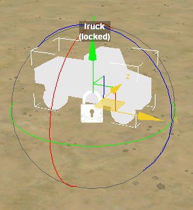
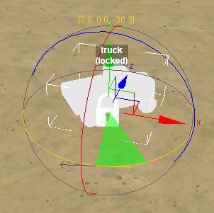
When dragging the mouse to rotate an object, your intuition is likely to drag the mouse in a circle, but that is not how the editor works. When you start dragging, the editor draws an opposing pair of arrows tangent to the circle at the location where you first clicked. Drag the mouse linearly in the direction of one of the arrows to rotate the truck. The more you drag, the more it rotates (even past 360°), although rotation stops when the mouse leaves the main view.
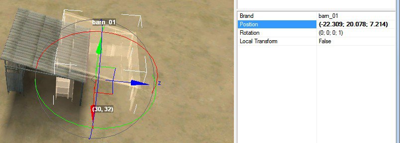
The object is surrounded by a virtual box that designates the boundaries of the truck in the X, Y, and Z axes. The corners of this box are shown with white lines. Because the box has a fixed orientation, its boundaries expand and contract to follow the corners of the object as it rotates.
Manipulate an Object in the Scene View
When an object is selected, a panel appears at the bottom of the Scene View showing all of the properties of the object. I call this the “property panel”.
The position of an object is listed as the “Position” property. The three values are its X, Y, and Z coordinates, each measured in meters. You can edit these numbers directly. Be sure to left click in the main view to commit your changes.
The orientation of an object is listed as the “Rotation” property. The four values are… weird. If you just want to make sure that an object is an exact E-W or N-S facing, first rotate it in the main view to be pretty close. Then edit the numbers next to Rotation to get it exact. You’ll want all the values to be 0, ±1, or ±0.707. For a 45° facing, the desired numbers are 0.383 and 0.924. Be sure to left click in the main view to commit your changes.
Editing and committing changes in the property panel is described in the “Edit Named Properties” section, previously.
The coordinate systems for position and rotation are described in more detail in the appendices of this guide.
Land and Do Land
The other property of interest for editing trucks is the Land property, which can be set as True or False. The equivalent of “Land” for plants is “Do Land”.
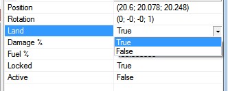
When the Land or Do Land property is True, the truck or plant is attached to the ground. A plant keeps its orientation when it is attached to the ground. For a truck, the editor tilts the truck so that its wheels make maximum contact with the ground.
When the Land or Do Land property is False, the truck or plant can be moved freely. It can be raised into the air, buried in the ground, and tilted to any orientation. In most cases, this will look unnatural and result in strange physics. But it can also be useful, e.g. to place a truck on a bridge.
Models don’t have a Land or Do Land property, but they have an additional context menu item for “Do Land”. When this is selected, the editor moves the model down until its basepoint (which may or may not be the bottom of the model) touches the ground. The model is not attached to the ground, however, and can still be freely manipulated from its new location.
When a truck is attached to ground, it orients itself for maximum contact. When a plant is attached to ground, its narrow base means that it makes good contact regardless of orientation. However, it can be difficult to cleanly place a model on uneven ground. Be sure to careful check around the base of the model for gaps and either re-orient the model or adjust the ground height until it ha a solid connection.
Local Transform
When moving and rotating plants and models, it can be helpful to manipulate them using their local axes rather than the global axes. The “Local Transform” option in the toolbar can be toggled by clicking it or pressing ctrl-L. Using local axes can make tilting more intuitive, and it can make it easier to line up repeated objects such as fences.
Select Truck Components
The previous sections described the steps to create and move generic objects. This section and the next one describe how to edit the properties specific to trucks.
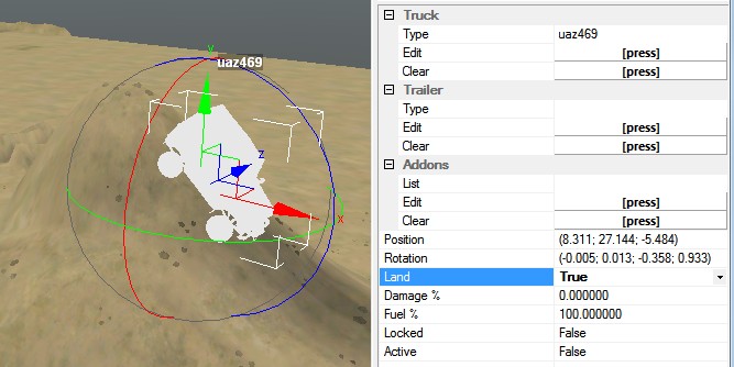
Choose the Truck Type
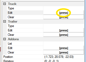
The primary property for any truck is its type. When a truck is selected, this property is the top one in the list of properties in the Scene View. To select the truck type, left click “[press]” for the “Edit” pseudo-property under “Truck”. This brings up a list of trucks from which you can choose your truck type.
Once a truck type has been selected, it appears in the properties panel, and the ghost view of the truck in the main view changes to reflect the selected truck type. However, the name of the truck won’t change in the main view or the Scene View until the truck is deselected.
You can return the truck to the generic truck type by clicking “[press]” for the “Clear” property under “Truck”. You can also choose a different truck type by clicking next to Edit again and choosing a new truck. Choosing a new truck type discards the previous selection, but keeps all other properties including trailers and addons.
The editor uses lowercase truck names that differ from the names used in the game. The appendices to this guide contain reference information for all trucks, including a mapping between the names used in the editor vs. the names used in the game.
In the truck selection dialog you can choose to select a trailer instead of a truck. If you select a trailer this way (instead of the usual trailer selection below), the trailer is parked by itself as if it is a truck. Logs can be loaded on this trailer as described in the addons section below.
Choose a Trailer
Selecting a trailer is performed much like selecting a truck, this time using the buttons under “Trailer”.
If you select a trailer that is not compatible with the truck type, the editor simply records the choice without any error notification. Refer to the “Truck Reference” sections to find the valid trailers for each truck.
The trailer is not drawn in the main view. You will have to use your intuition about its length to ensure that it doesn’t overlap any other objects.
Choose Addons
Selecting addons is also performed in a similar manner using the buttons under “Addons”. Unlike for trucks and trailers, however, this window allows you to select multiple items before clicking “OK”. Clicking an addon in the dialog once selects it. Clicking it again deselects it. Selected addons are indicated with a black border.
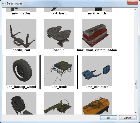
If no addons are selected, or if all addons are deselected, the “OK” button is greyed out. You can still press the enter key, but it has the same effect as “Cancel” when no addons are selected. The only way to clear all addons is to click the “[press]” text next to Clear in the Addons category.
If you select any addons that are incompatible with the truck or with each other, there is no error notification. Refer to the “Truck Reference” sections to find the valid addon combinations for each truck. The order of addons doesn’t matter, as long as the necessary prerequisites are somewhere in the list.
Addons are not drawn on the truck in the main view.
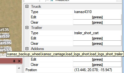
The list of addons may be longer than will fit in the properties panel. Hover your mouse over the list of addons to get the full list in hover text.
If a fuel or repair addon is selected for a starting truck (see “Starting Trucks” below), the game initializes the addon to be empty. For a non-starting truck the game initializes the addon to start with about half its capacity, plus or minus a small random amount. There is no way to adjust this value.
Logs can be loaded onto the truck as an “addon”. This works for logs in the bed of a truck or stretched between a log carrier and a beam-type cart. Logs can also be loaded in a stand-alone trailer that is not attached to a truck. However, logs cannot be loaded into a trailer that is attached to a truck. (They simply don’t appear when you play the game.) Note that there are multiple models for each of the log types. Use the “Truck Reference” sections to find the correct name for the logs corresponding to your truck.
Edit Other Truck Properties
Damage and Fuel
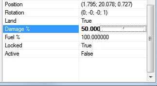
By default, trucks start with zero damage and full fuel. The “Damage %” and “Fuel %” truck properties allow you to start the truck with more damage or less fuel.
Even if the Fuel % property is 100%, a truck will not start with more than 200 liters of fuel, as if it had been refueled at a garage. The amount of fuel on board is the maximum of (capacity * fuel %) or 200 liters. Fuel addons are not affected by the Fuel % property.
Damage % and Fuel % have no effect on trailers, even stand-alone trailers.
Locked and Unlocked Trucks
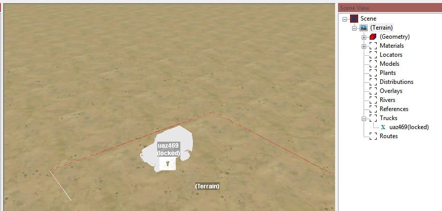
The “Locked” property determines whether a truck is locked at the start of the map. If a truck is locked, the player cannot use the navigation map to switch into it.
Setting the Locked property to “False” removes the “(locked)” suffix from its name and removes the padlock icon from the main view.
If a truck is actually just a trailer, the Locked property has no effect in the game.
While playing the game, a player can unlock a truck by approaching it in another truck. Or, if the truck is cloaked by a watchpoint, approaching the watchpoint to remove the cloak will also unlock the truck.
Trucks close to the active truck are also unlocked automatically, as described in the next section.
Starting Trucks
You can set one truck’s “Active” property to “True”. This is the truck that the player will start in when playing your map.
When you change a truck’s Active property to True, the editor will automatically change the previous active truck to inactive. However, it is possible to end up with multiple active trucks in other ways, such as by duplicating an active truck. In this case, the game uses only the last truck marked active in the list of trucks in the Scene View, and it treats the other trucks as inactive.
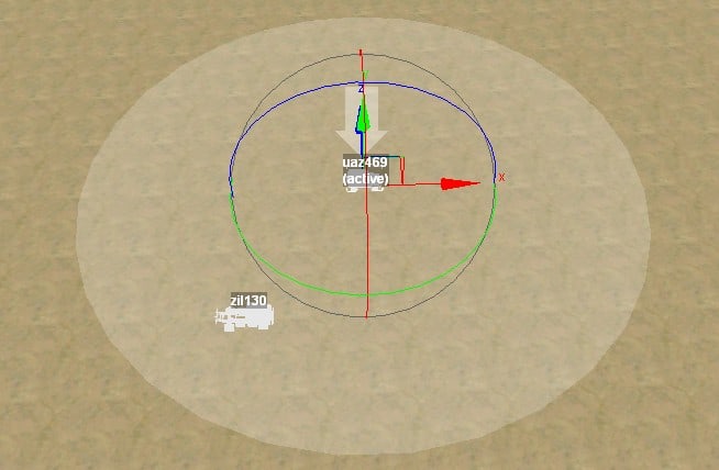
The active truck and all trucks within 32 meters of it are the starting trucks for the map. The game automatically unlocks these trucks, regardless of how they are designated in the map. It also unlocks any garage within this radius. The 32m radius is highlighted when the active truck is selected.
The game sums the balance points for the starting trucks and allows the player to substitute different trucks for any or all of them. If the map designates starting trucks worth N balance points, the player may substitute trucks up to a total of N+1 balance points. However, if the map starts with fewer than 4 balance points, the player is always allowed to substitute trucks to a total of 5 balance points.
Although the player can replace each of the starting trucks, she cannot add or remove starting trucks, regardless of the total balance points.
If the player replaces the active truck with a different one, she will start in that truck. Addons or trailers will be lost for any truck that the player replaces.
Although there is no set limit on the number of starting trucks, too many will overflow the map selection screen and limit the player’s options.
The game lists the starting trucks in the same order in which they are in the Scene View. The player probably expects to start in the first truck listed, so it’s a good idea to make that one the active truck.
Trucks with Zero Balance Points
All trailers and some trucks have zero balance points. The game does not count these as starting trucks, and the player cannot replace them. But if there are no starting trucks, then the map cannot be played normally; it can only be played in the proving ground. If there are at least some starting trucks with positive balance points, the player will start in the active truck, even if it has 0 balance points itself. All trucks within the 32m radius of the active truck are unlocked, even if they have 0 balance points.
If a truck is left on the map with no type, then it will not exist in the game. However, if this truck is one of the starting trucks, it appears as “[NO TRUCK]” in the starting truck list, and the player is given the opportunity to replace it. This is an exception to the usual behavior for trucks with no balance points. If the active truck has no type and the player does not replace it, the game selects another starting truck to start in. If none of the starting trucks has a type, the player must replace at least one truck before the game will allow the map to start.
Hand Edit the XML
The properties for all of your trucks (and other data) is saved in your map’s XML file in the prebuild directory. Editing the XML by hand is useful for tasks that are difficult or impossible to do in the MudRunner Editor. For example, you can rearrange the trucks so that the active truck is first, followed by the starting trucks. Or you can globally change the Locked property to False for testing purposes.
More detail about hand-editing the XML file appears in the appendices.
Edit Other Model and Plant Properties
Scale
Each model and plant has a default size, but you can adjust its size to make it larger or smaller. This adjustment factor is the Scale property.
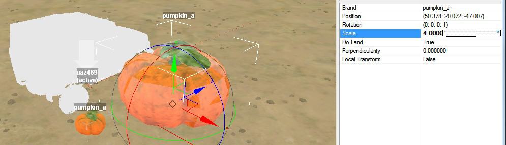
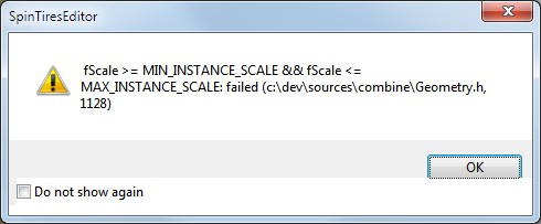
For models and plants, you can adjust the scale directly in the property panel. Alternatively, you can left click in the diamond at the center of its axes and drag up or down to increase or decrease the scale, respectively. There is no predefined range for the scale of a model. The scale for plants is limited to the range from 0.25 (smallest) to 4.0 (largest). Warning: there is a bug in the editor that causes it to display an error if the scale is exactly 0.25, even though that value should be allowed.

Perpendicularity
Especially for bushy type plants, it may make sense to have them grow perpendicular to a hillside rather that vertical. You can rotate the plant by hand, but for this task it is easier to adjust its Perpendicularity property.
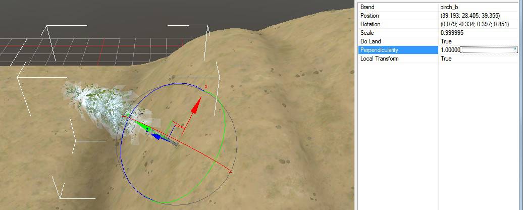
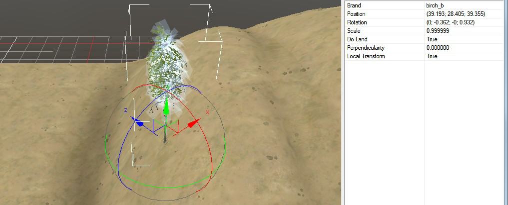
When the perpendicularity is 1, you can rotate the plant around its perpendicular axis, but you can no longer tilt the plant freely. Reducing the perpendicularity restores your ability to tilt the plant, but it will not automatically return to its former orientation. If the perpendicularity is between 0 and 1, the plant will resist your attempts to tilt it. Set the perpendicularity to 0 to restore unfettered rotation.
Brand
The brand field for a model is editable. However, when you enter a new value, even if it’s a correct model type, the editor displays an error dialog and reverts the value.
On the other hand, if you edit the brand field for a plant, the plant changes to the new type. If the new brand isn’t a valid type, however, the editor display a series of error dialogs and erases the plant from the main view.
Undo Position, Rotation, and Scale
You can press ctrl-Z to undo position, rotation, and scale changes that were made in the main view. The most recent change is undone. You can press ctrl-Z multiple times to undo multiple changes.
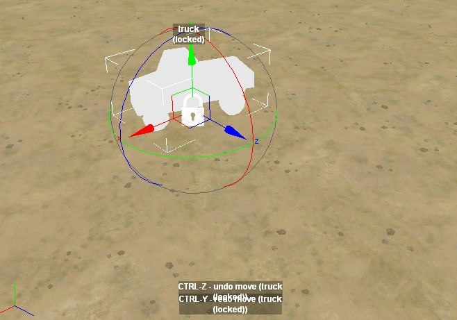
After undoing a change, you can redo it by pressing ctrl-Y. Press ctrl-Y multiple times to restore multiple changes, continuing until the last change before the undo. This can include the last change made in the main view even if it wasn’t confirmed yet.
Undo and redo can be used for changes to both simple objects (such as trucks) and to the points of spline objects (such as roads).
If changes were also made in the Scene View, these changes are skipped over in the undo/redo sequence. Undo and redo simply reset the position, rotation, and scale properties to whatever they were at the end of a change in the main view.
Note that undo and redo do not affect properties other than the position, rotation, and scale. For example, if the most recent change was to set the Land property to False in the Scene View, pressing ctrl-Z will undo the previous position change in the main view as well as it can, but the truck will continue to be attached to the ground.
If you’ve moved more than one object recently, undo and redo will switch the selection among the objects as needed in order to update their properties.
The undo history is discarded when you Rebuild Terrain.
Special Models
There are many static models. Some of them have lights, wire attachment points, or other extra features. Most models are completely immobile, although a few can be knocked over or broken.
A few models have more extensive gameplay logic built into them. Those models are described below.
Blockposts
The blockpost_a, blockpost_b, and us_checkpoint models include a moving gate. By default, the gate opens for trucks as they approach. But when a truck approaches carrying logs, the gate stays closed. This forces the player to take an alternative route or perhaps to only use certain log stations to supply certain lumber mills.
Additional game logic prevent a truck from trying to cheat the system, but a determined player can still get logs across using a crane. Cheating the blockpost is annoying and slow, but you’ll probably want to make sure that the alternative route is not even more annoying and slow.
Individual Logs
The log_long_a, log_medium_a, and log_short_a models are individual logs that can be placed on the map. A truck with a crane can pick these up much like it picks up logs from a kiosk, except that the individual logs never replenish themselves.
Log Kiosk
The logs_kiosk model is a special model from which the player can retrieve logs of her choice. When the player’s truck approaches to within 10 meters, an interface appears next to the kiosk giving a choice of logs to retrieve.
Log Scavenge
The logs_scavenge model is a special model that gives the player random logs. The game tries to keep logs available at three log scavenge locations at a time, so your map should have at least that many. (When I tried with fewer, the game seemed to get confused about whether certain log scavenge locations had logs or not.)
Test Your Map
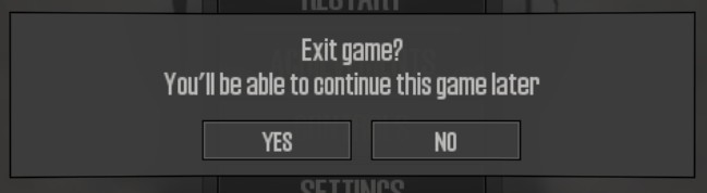
Now that you have something on your map, you may want to test it in the MudRunner game. For all testing methods, you must exit the game to the main menu and restart the level to load your changes. If you continue the level rather than restarting it, you will get a confusing mix of map attributes, some with your latest changes and some from the previous saved game.
There are four ways to test your map, each with advantages and disadvantages. The first and last ways are the easiest to do and give you the full range of testing possibilities. The middle two ways add some “happy middle” testing methods, but require a bit of fiddly configuration work.
Go Through the Proving Ground
The quickest testing method to get started with is to step through the proving ground to test the map. Using this method, the game already knows where to look for your map files created by the editor.
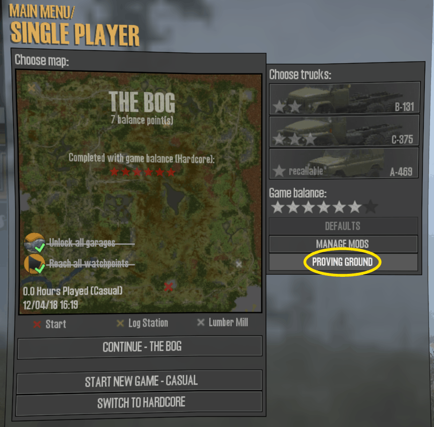
Start MudRunner and select “Single Player”. Then, below the truck selection area, click on “Proving Ground”.
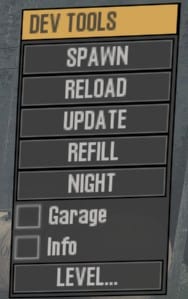
The game will start in the built-in Proving Ground map with a Dev Tools menu in the upper right. Click “LEVEL…” in the Dev Tools menu.
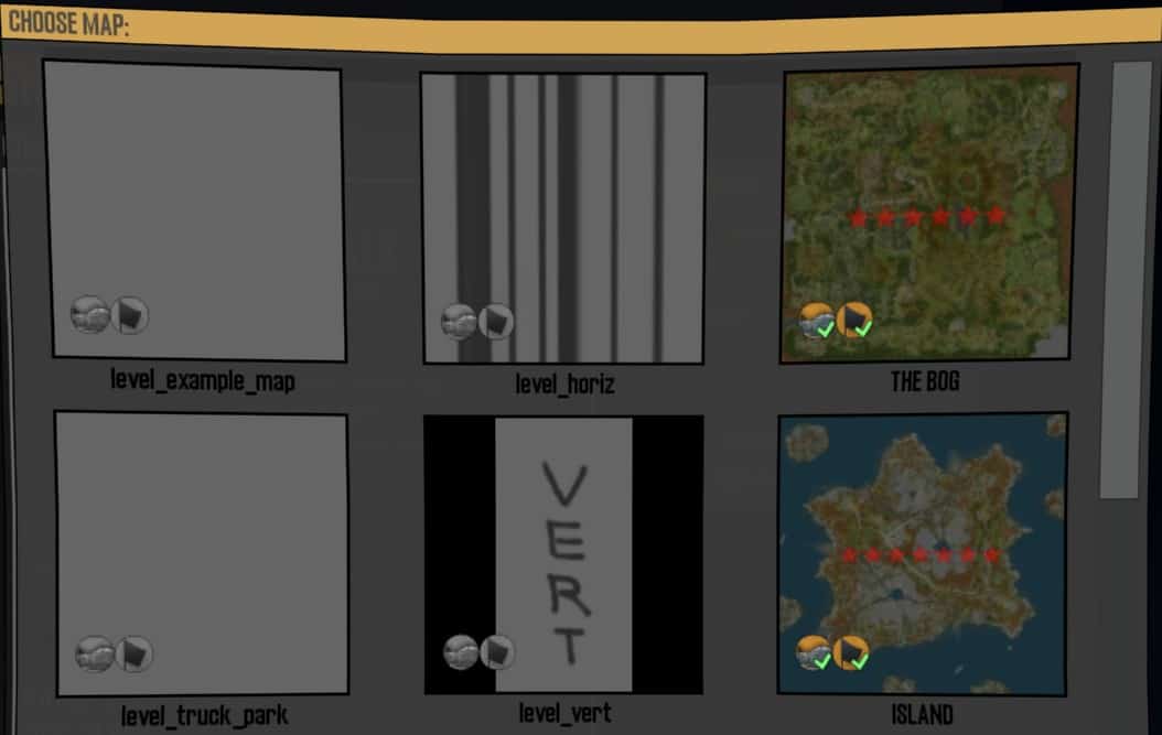
A dialog box lists all of the maps in the editor’s _mods area. Choose your map to launch it.
When using this method, you are playing your map in the proving ground framework. The Dev Tools menu is available for you to switch between night and day, spawn new trucks, change addons anywhere, etc.
If you make a change in the map editor, you don’t need to exit the MudRunner game entirely. Just exit back to the main menu and step through the build-in proving ground again to reload your map.
The proving ground has advantages for testing:
- You have access to the Dev Tools menu.
- If your starting trucks aren’t configured, the game will choose one for you.
It also has disadvantages:
- It takes multiple steps to restart a map after changing it in the editor.
- You cannot recall a truck or recover a truck to a garage.
- You can’t check the balance points of your map.
- Your progress isn’t saved when you exit the map.
- The game doesn’t check whether custom assets are in the correct mod directory.
- The Dev Tools menu gets in the way if you want to take screenshots including the HUD.
Shortcut Past the Proving Ground
When repeatedly testing your map, stepping through the built-in Proving Ground map can get aggravating. You can shortcut this process by configuring the game to treat your map more like a regular map. You do this by adding a pointer to your mod in the game’s Config.xml file. This file is in the top level of the MudRunner application directory. It probably has a path similar to this:
c:/Program Files (x86)/Steam/SteamApps/common/Spintires MudRunner/Config.xml
This file includes paths to the various media directories used by the game. The published directories are bundled up as ZIP files, but the game can also read regular directories. Among the other paths, add a line to point to your mod directory, e.g.
<MediaPath Path="c:/Program Files (x86)/Steam/SteamApps/common/Spintires Mudrunner - Editor/Media/_mods/5e5c745c" />
(For those of you who just copied and pasted that line verbatim without changing the mod directory name, I’m going to laugh at you when you complain in the comments.)
Save the file and restart MudRunner. You can now select your map among the standard published maps.
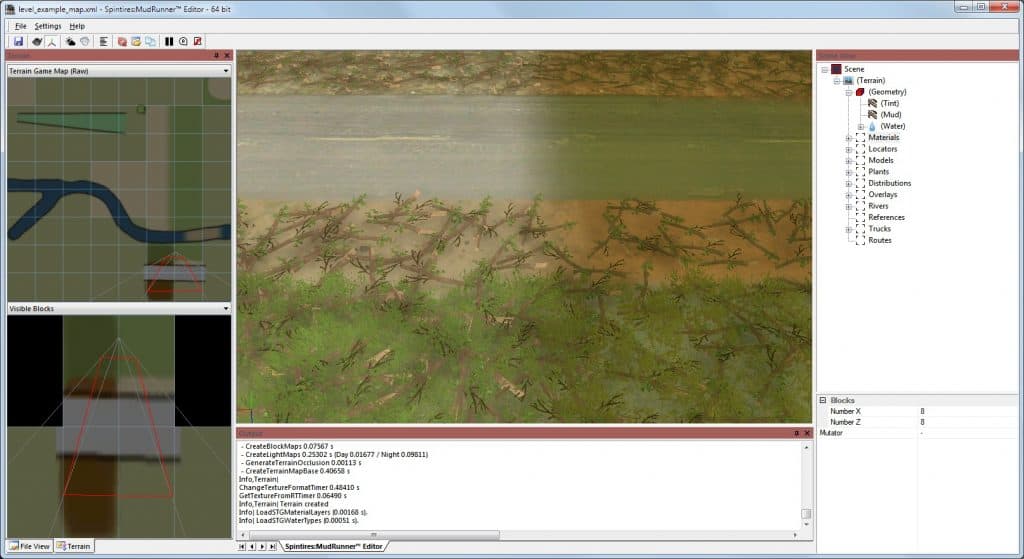
If you haven’t created any terrain yet, the preview of the map will be featureless. It will look more interesting as you add terrain features to your map.
Although this testing method bypasses stepping through the built-in proving ground, the game still recognizes it as a map in the custom mods area, so it gives you the Dev Tools menu as before.
Summary of advantages compared to the previous testing method:
- A bit quicker to select a map.
- Can check balance points and starting truck selection before starting the map.
- Game checks that all custom assets are in the mod directory.
Summary of disadvantages compared to the previous testing method:
- Requires editing the Config.xml file.
- Requires that the level has an “active” truck.
Pretend that your Map is Published
The game puts the Dev Tools menu on any map under the _mods directory. To avoid that and treat the map more like a published map, you can add a link to the _mods directory using a different name.
Since you’ll be making the link in the editor’s application directory, you’ll need a command shell with administrative privileges.
In the command shell, change to the MudRunner Editor’s Media directory and use mklink to create a link to “_mods” with a different name. E.g.
cd C:\Program Files (x86)\Steam\SteamApps\common\Spintires Mudrunner - Editor\Media mklink /d normal _mods
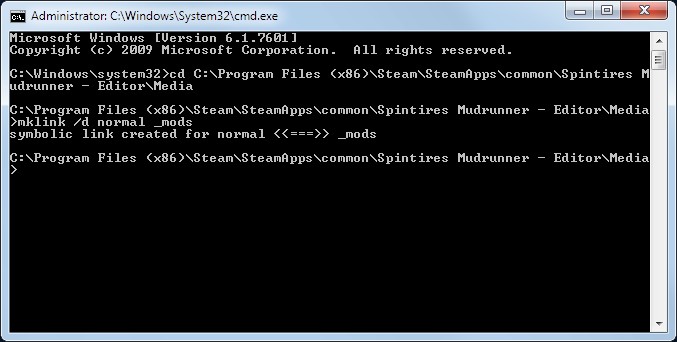
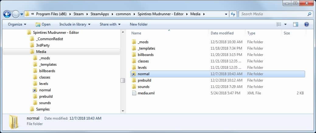
You now have a link to your _mods directory with a different name. This link visually looks like a normal Windows shortcut, but unlike a normal shortcut, it actually works when the MudRunner application reads it.
Finally, you can update the MudRunner Config.xml file as in the previous testing method, but this time using the new path. E.g.
<MediaPath Path="c:/Program Files (x86)/Steam/SteamApps/common/Spintires Mudrunner - Editor/Media/normal/5e5c745c" />
You can now select and start the map the same as in the previous method, but this time the game will not add the Dev Tools menu. And when you exit the game, it will save your progress. This is especially valuable later in the testing process when you’re checking the gameplay of the entire map.
Because the map can be continued, the game also selects the map as the default choice the next time you select a map, which speeds up the testing process a little. However, you will want to select “Start new game” if you have made any changes. Otherwise you will end up with an odd mix of old map features that were recorded in your save file and features that were loaded fresh in the new map.
A published (or pretend-published) map also has a new option on the game menu. Choose “Restart” to reload the map, including any changes you may have just made in the editor.
Note that if MudRunner sees the same map via two different paths, it will only show you the “published” map. This means that you will not be able to test your map in the proving ground while pretending that it is published. Quit the game and update the path in Config.xml to switch between “published” and “proving ground” testing.
Summary of differences compared to the previous testing method:
- Restarting a level is faster.
- You can recall a truck or recover a truck to a garage.
- You don’t have access to the Dev Tools menu.
Publish your Map Privately
The final testing method is to actually publish your map. Don’t worry, though, Steam lets you keep it private so that only you can play it. You can also let your friends play it if you want. Great for testing multiplayer!
Instructions to publish your map are in the next section.
Publishing your map through the Steam Workshop gives it a randomly generated name that you will never see. This helps ensure that the game can keep your map separated from another that might have used the same player-visible name. As a happy bonus, it means that you can still test your map in your local files, since the game sees it as having a different level name.
Publish Your Mod
This guide hasn’t taught you enough yet to make a quality map. But since publishing your map is a useful way to test it, we’ll cover it now. This also gives you a preview of what to expect when you publish your map for real.
If you’re revisiting this section because you’re ready to publish your finished map, there are some areas you’ll want to review to make sure your map quality is as good as it can be:
- Rebuild Terrain to ensure that everything is drawn in its finished state with shadows, etc.
- Check all critical boundaries of distributions to be sure no plants are growing through models, on roads, etc. (These may all need to be rechecked after each change and Rebuild Terrain.)
- Check all roads for tilting, and check that all intersections look reasonable.
- Check around river junctions for unnatural bumps in the water height.
- Check that all models are properly placed with no gaps to the ground at any corner.
You should probably play through your entire map at least once as well to make sure that it all plays as expected. Some things that are hard to see in the editor such as a misplaced tree or a tilted road are very evident when playing the game, and these are the things you most want to fix.
If you are used to playing exclusively in casual mode, do keep in mind players who play in hardcore mode. Log stations do not exist in hardcore mode, so you must include log kiosks if you don’t want angry players. Be sure that the log kiosk radius doesn’t overlap the log station locator.
Conversely, if you are used to playing in hardcore mode, keep in mind players who play in casual mode. Although casual players can use a log kiosk, they probably don’t want to. Include log stations if you don’t want annoyed players. Be sure that the log station locator doesn’t overlap the log kiosk radius. Keep in mind also that there is a bug when recovering to a rectangular garage that you might not have noticed if you’re used to hardcore mode. Make sure your garage locators are square.
A list of all game bugs to avoid in your published map is in the reference sections of this guide.
Name Your Map
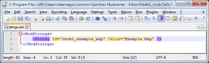
Before publishing your map, you’ll want to give it a proper name with appropriate capital letters and spaces. To do this, edit the strings.xml file in your mod directory. This can be done by double-clicking the strings.xml file in the editor’s File View. If you have an XML editor installed (such as Notepad++), it will open the strings.xml file. Edit the file with your lowercase map name and with a proper name. This is the name that the game will display when selecting the level.
If your mod contains multiple maps, add lines to strings.xml to give a name to each one.
Unfortunately, there is no multi-language support for mods. The MudRunner publishers recommend naming your map in English.
Publish Your Mod
You are now ready to publish your map. Technically speaking, you don’t publish just a map, but instead you publish the entire mod that the map is part of. To publish the mod, right click on it in the editor’s File View and select “Publish Mod…” This brings up a dialog window where you can make your publishing choices.
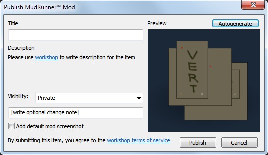
The “Title” is the name for the mod in the Steam Workshop. If the mod contains only one map, it makes sense to name the mod the same as the map.
You can also set the visibility of the mod in the Steam Workshop so that only you can see it, your friends can see it, or everyone can see it.
The “Preview” panel on the right shows your mod’s icon that will be generated for use by the Steam Workshop. Click the “Autogenerate” button to generate a preview of your map(s) as the icon. This same image is also added as a sample screenshot in the Workshop if you check the box marked “Add default mod screenshot”. These two images are saved in your mod directory as preview.png and preview_wide.png if you wish to edit them by hand.
You’ll probably want that link to your mod in the workshop, so click it now to open it in a web browser before closing the dialog.
Finally, click “Publish” to publish your mod and close the dialog.
If you have extra files in your mod directory, you may get some warnings about unrecognized file extensions. You’ll have to click through the warnings, but be secure that the editor will not include these files in the published mod.
At the Steam Workshop website you can edit the description of your mod, add screenshots, etc. One thing you cannot do at the website is to change the icon for your mod. For that, you’ll need to update preview.png and publish your mod again.
After publishing your map, be sure to “Subscribe” to it at the Steam Workshop website to have it show up in your game. It appears that Steam will not push updates to your computer after you have subscribed. Therefore, after publishing any changes, you need to Unsubscribe to delete the mod from your computer, wait a few seconds, and then Subscribe again.
Dealing with Editor Errors
When the editor encounters a problem, it will often print a message into the Output view and continue. However, for some problems, the editor pops up an error dialog and stops processing.
This section will prepare you to deal with these errors in order to salvage your work.
Skip the Error
If you simply click “OK” in the dialog box, the editor will continue as best as it can. This often means that the feature with the error simply isn’t drawn. You can also press the enter key or escape key to skip past the dialog box.
If you click the checkbox in the dialog to “Do not show again”, that type of error will neither pop up the error dialog box nor cause the editor to stop processing. This setting persists until you quit and restart the editor. You can still see the errors in the Output view.
![]()
On the other hand, if you do not click the checkbox, the next occurrence of the error in the same processing sequence causes the editor to stop processing, but without popping up a dialog box. The only evidence that the editor has stopped is that the progress bar stops moving. Press the escape key to skip the error and continue processing. If there are many errors, you can repeatedly tap the escape key or even hold it down to skip them quickly. This often causes the editor to quit, however.
Correct the Error
Once past the error, carefully consider whether you want to save. If you have a lot of unsaved work, you could lose it if the editor crashes. On the other hand, if you don’t save and the error is difficult to solve, you can reload your old state to (hopefully) discard the source of the error.
You can often guess the source of the problem based on what you’ve been editing recently and based on the error message. (The above examples suggest that a object’s scale is out of the allowed range.) In that case, simply find the problematic feature and edit it to not have the error.
If you still can’t find the source of the error or if the editor crashes too often for you to track it down, the next step is to hand edit your map’s XML file. First make a copy of the XML file, then start chopping out large sections until the error stops occurring. Then add smaller sections back in until it recurs. Eventually you should find the problematic feature, and hopefully you can then figure out what is wrong with it. How to hand edit the XML file is described elsewhere in this guide.
An error can occasionally creep into the compiled DDS or STG files so that the editor crashes every time you try to rebuild the terrain. This appears to be quite disastrous, but is actually easy to correct. Simply delete the DDS and STG files from your mod’s “levels” directory before rebuilding the terrain. You will get one error dialog asking if it should recreate the STG file, and then hopefully it will be back to normal.
Edit a Bitmap Property (Tint)
I know you want to get started editing the terrain height, but it’s easier to explore the concepts on flat ground first. The tint tool allows you to darken the terrain where desired. It’s intended for use late in the design process as you tweak the cosmetics of your map. But it’s also a useful tool early in the process to sketch the rough layout of your map directly onto the terrain. We’ll use it as our example bitmap property for training purposes.
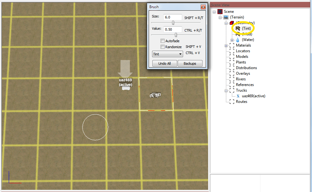
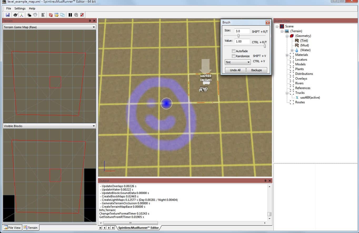
Left click “(Tint)” under “(Geometry)” in the Scene View to access the tint tool. A Brush window appears, and the mouse is now surrounded in the main view by a circle representing the brush. (The Brush window is not modal; you can and will perform actions outside of it while it is visible.)
Right click and drag in the main view is the method for painting with the brush, but the initial brush values are set up to have no effect. I’ll get to that in a minute. A simple left click in the main view selects something else to edit and thus closes the tint tool. However, the usual left-click-drag navigation methods still work without closing the tint tool.
Brush Size
You can adjust the size of the brush in the brush window:
- Type in a new size value directly.
- Click and drag the slider under the Size.
- Click the slider and use the left and right arrow keys and the Home and End keys.
- Click to the left or right of the slider to decrease or increase the size.
- Press shift-R to decrease the size and shift-T to increase the size.
The shift-R and shift-T keybindings are handy because they also work in the main views. You don’t have to move the mouse to the Brush window.
The size value is the radius of the brush in meters. The minimum brush size is 0.5 meters, but that’s fine because the finest resolution of the tinting is only two-thirds of a meter. In other words, the map keeps the amount of tint for just three pixels for every 2 meters in the X and Z directions. However, the game engine smoothly shades the tinting between these pixels so that the terrain doesn’t look pixelated.
Brush Value
The Value field is unintuitive at first. It does not directly set the color of the tint to apply with the brush. Instead it determines the relative change that the brush applies to the existing tint. The value can be set in the range of 0.0 to 1.0. A value of 1.0 means “increase the tint the maximum amount”. 0.0 means “decrease the tint the maximum amount”. The initial value of 0.5 is right in the middle and means “don’t change the tint at all.”
You can adjust the value in the same way as adjusting the size, except using ctrl-R and ctrl-T as the keyboard shortcuts to decrease or increase the value.
For values greater than 0.5, a fuzzy blue blob appears in the middle of the brush circle to represent the color that will be brushed. The brush color fades out toward the edge of the circle to allow a soft edge to your tint. (Hard edges look unnatural in most terrain.) For values of 0.5 or less, the the fuzzy block is black. The intensity of the blue or black blob depends on the distance of the value from 0.5.
Draw Tint
To start tinting, change the value to 1.0, then right click and drag in the main view.
While using the tint tool, the current tint state is highlighted in blue. Select anything else (e.g. by left clicking the terrain) to close the tint tool and commit your changes.
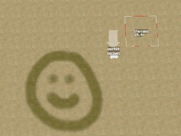
When the tint tool is not active, the tint shows its normal color. This color varies depending on what terrain is being tinted, but it is usually a dark greenish brown.
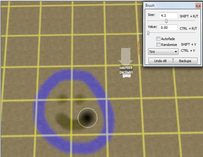
In the following image, I have set the brush value to 0 and erased the features in the middle of the circle. The current tint state is highlighted in blue, meaning that if I commit my changes, only the circle will be tinted. The old tint remains visible in its normal brown color until I commit my changes. Or I can click “Undo All” in the brush dialog to revert to how things were when I opened the tint tool.
What Gets Tinted
The tint is applied to ground materials, roads, grass, and plants, but not models. It also makes a roots overlay disappear in the tinted region.
Restore from Backup
The editor doesn’t have a strong undo feature for terrain editing. It is easy to discard the current set of edits, but that’s it. However, the editor does keep a copy of the bitmaps for 7 previous tints. Click the Backups button in the brush window to open Windows Explorer in the directory holding these bitmaps. Then close the tint tool because you won’t want to save any new edits while restoring a backup tint.
_tint_src.tga is the initial (blank) tint for your map. For the other files, the highest numbered tint is the most recent past tint (not including the current tint).
If you have a program to view TGA files (such as Irfanview or Gimp), you can browse these files to find one that you’d like to restore. You may notice that the bitmap is upside down. I describe why in the “Position Coordinate Systems” section in the appendices.
You can restore a tint file by copying it from the backup directory to your map’s bitmap directory, e.g. …/5e5c745c/prebuild/level_example_map. In that directory, delete the _tint.tga file (because you didn’t like that tint) and rename the copied file to _tint.tga in its place. Make sure that the editor’s tint tool is closed so that you don’t accidentally overwrite this file.
Unlike when you update the map’s XML file, the MudRunner Editor won’t automatically notice the changed file. Right click in the main view and select “Rebuild Terrain” to redraw the map from the files.
Autofade
The Autofade checkbox is mostly useful for drawing tire tracks in mud, not tinting, but you can experiment with it here. With Autofade enabled, when you right click and begin dragging in some direction, the editor adds a tail on your tint that fades in as if you had slowly lowered the brush onto the terrain while approaching the spot where you actually clicked. And when you let go of the right mouse button, the editor adds a tail that fades out as if you had slowly lifted the brush while continuing to drag in the most recent direction. The length of the tail is about 10x the width of the brush.
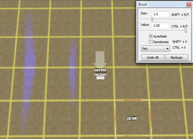
Randomize
The Randomize checkbox is most useful for the plant distributions drawing tool, but you can experiment with it here. With Randomize enabled and a value greater than 0.5, right click and drag increases the randomness of the tint under the brush. For value 1.0, the randomness is maximized, meaning that every pixel has a random tint from 0% to 100%. For values between 0.5 and 1.0, the randomness is biased toward whatever the tint was before. However, the more you drag the brush across any pixel, the more that the randomness will accumulate.
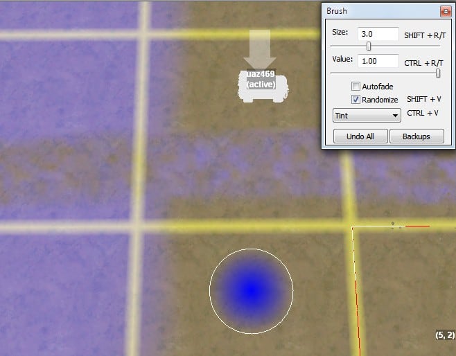
The Randomize checkbox has no effect if the value is less than 0.5. Drawing with a value less than 0.5 simply reduces the tint as usual.
Dropdown Menu
Just below the Randomize checkbox is a dropdown menu that says “Tint”. There are no other options for the tint tool; it just lets you know that your current brush is for tinting. When using other tools, this dropdown menu will have other options that you can switch between while drawing.
Edit Terrain Height
The geometry tool allows you to adjust the height of terrain. Its brush menu has two subtools, “Height” and “Flatten”, which can be toggled with ctrl-V. We’ll start with height.
Edit the Height
Similar to the tint tool, the value field ranges from 0 to 1, with low values leading to decreased height, and high values leading to increased height. Unlike the tint tool, the values of 0 and 1 to not immediately set the height to the minimum or maximum value, but they do often change it more rapidly than you’re prepared for. Use extreme values with care.
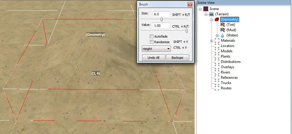
Values in the range of 0.40 to 0.60 usually produce better results. Drag the brush multiple times over an area to build up or reduce its height further. Be sure to rotate the camera often to make sure you’re not creating extreme terrain that isn’t obvious from a single view.
Recalculating shadows is slowish, so the editor doesn’t automatically do so after the height is edited. Use the context menu to Rebuild Terrain to recalculate shadows (and everything else) for the entire map, or use Rebuild Visible to recalculate only within the field of view of the camera (whatever is highlighted in the Visible Blocks panel).
Old shadows that have not yet been recalculated may be deceptive. Be wary that they may indicate height contours that no longer exist.
Height Difference Limit
There is a limit to the height difference within one terrain block, usually 16 meters. You can draw it taller (as in the left screenshot below), but when you exit the geometry tool, it will flatten down to the limit (as in the right screenshot).
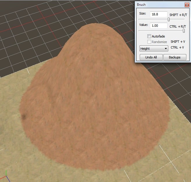
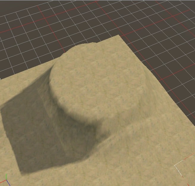
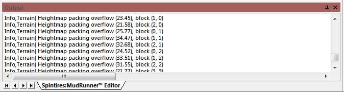
The editor continues to save the height that you asked for. If you edit the height with these terrain blocks again, it will show you your desired height, again flattening it out when you exit the tool.
If the editor gets overwhelmed by extreme height changes, it may occasionally tear gaps in the terrain as the edges of terrain blocks fail to line up. You can fix this by rebuilding the terrain.
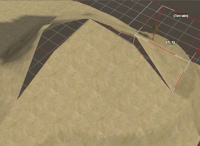
Flatten the Terrain
Repeated passes with the height brush tend to result in lumpy terrain. You can smooth this out by pressing ctrl-V to switch to the flatten brush.
Values have a different meaning for the flatten brush. A value of 0 doesn’t flatten at all. A value of 1 doesn’t flatten entirely, but it does flatten quite a lot.
The flatten tool works differently in the direction of the dragged mouse vs. perpendicular to the dragged mouse. The flatten effect is strongest perpendicular to the dragged mouse, as the flatten tool redistributes dirt from the high side to the low side. With a value of 1, this almost completely flattens the terrain from side to side, although there is some fall off at the sides where the fuzzy blob weakens the flatten effect.
In the direction of the dragged mouse, the flatten tool mostly follows the terrain rather the lifting or squashing it wholesale, but the brush does push a bit of dirt in front of it to fill in holes and somewhat flatten the terrain.
With a value of 1, the tool does a great job of flattening a road bed. Simply drag the mouse along the path of the road, and it flattens it side to side (as you’d expect a road to be) while following the terrain along the length of the road (also as you’d expect). Avoid reversing the mouse along the road, since that will leave a moraine of dirt at the edge of where you turned around.
When dragging long distances like this, you can let go of the right mouse buttom, then ctrl-left drag to shift the terrain or use the mouse wheel to zoom in or out. Since these navigation controls operate relative to the current mouse position on the terrain, the mouse will stay in the exact same position on the terrain. You can then right click and begin dragging again from where you left off without a hiccup.
Less extreme values of 1 can be used to smooth the terrain without completely flattening it. With low values, you can make multiple passes over the same terrain to achieve the desired smoothness, using linear, circular, or random motions as you feel appropriate. The result will be terrain that retains its hills and bumps, but doesn’t have unnatural looking extreme terrain.
When editing with the height tool, the map tends to acquire curled edges. These are difficult to fix with the height tool because any attempt to raise or lower the height at the edge also raises or lowers the height near the edge just as much. The flatten tool can be used to straighten these edges.
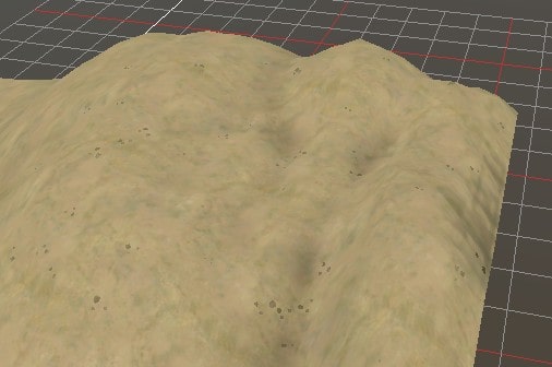
Edit Mud
Mud is tricky to get right. Expect to experiment a lot to get a feel for it.
Note that many of the terrain materials are already a little soft, including the default dirt material. This means that if a truck drives over it repeatedly, it will eventually cut ruts into the terrain and lose traction. Adding mud makes the material even softer and more slippery.
Expand the “(Geometry)” category in the Scene View and click “(Mud)” to start the mud tool.
The mud tool has two brush types, “Automatic” and “Extrudes”. For both brushes, values less than 0.5 decrease the amount of mud, and values greater than 0.5 increase the amount of mud.
The brush for mud allows for finer detail and is half the size of any other brush for the same “Size” value. This means that the mud brush size effectively measures the brush diameter (whereas all other brushes measure the brush radius).
Extrudes Brush
Painting with the Extrudes brush softens the terrain in the painted area, making it easier for a truck to sink into it. The most obvious visual change is that while editing with the mud tool, a brown tint covers the terrain block, indicating that mud is present. If you look closer, you can also see thin white lines extending down from the terrain surface where you painted. The length of each line represents the softness and depth of the mud in that area. It can be helpful to have an object nearby to use as a reference for scale.
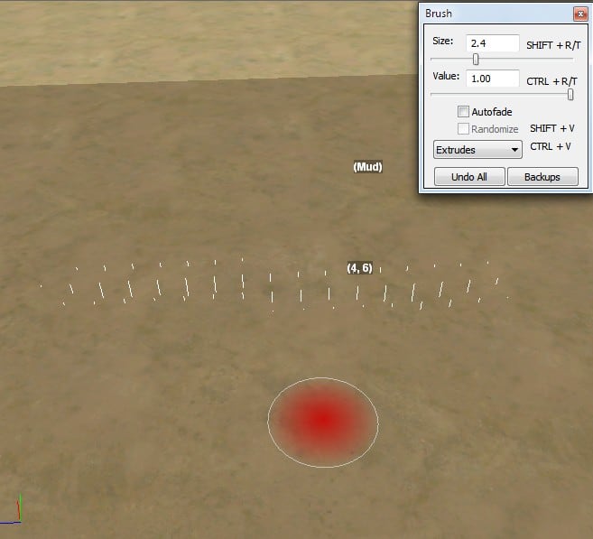
If you left click to exit the mud tool, there is no visual indication of the mud at all. This is true within the game as well. To make the mud visual, you’ll need the Automatic brush. The Extrudes brush has a red fuzzy blob in it which I interpret as a “danger” signal that you are creating invisible mud.
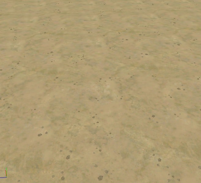
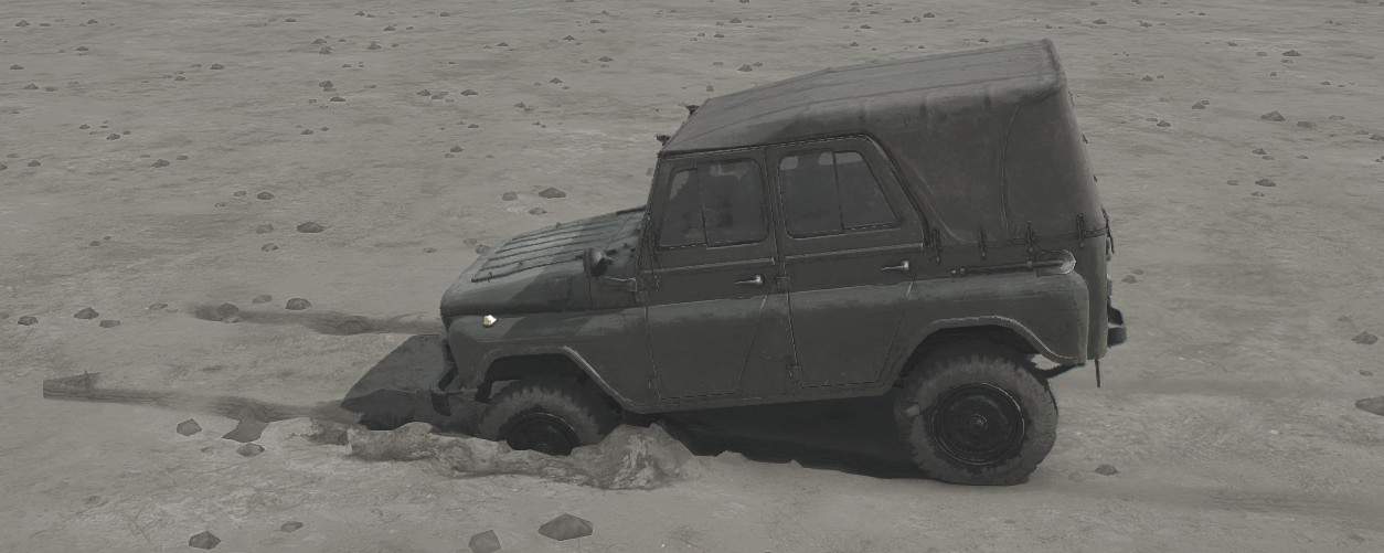
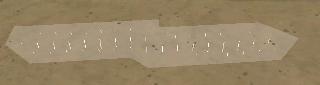
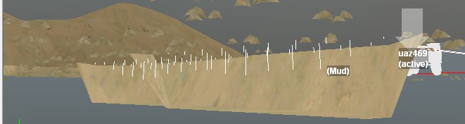
Automatic Brush with Size > 2.5
The mud tool’s Automatic brush has very different behavior depending on whether the brush size is greater than 2.5 or less than or equal to 2.5.
When the Automatic brush size is greater than 2.5 (meters), it behaves much like the Extrudes brush except that it also creates a visual representation of the mud.
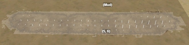
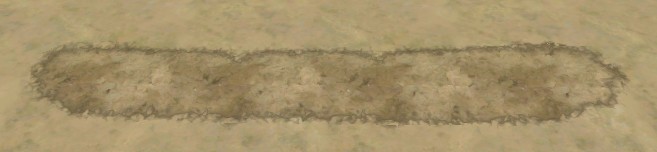
When the Automatic brush size is equal to or less than 2.5 (meters), it carves ruts in the mud similar to tire tracks. The mud created is lower in the center and slightly higher than the terrain at the edges, as if a truck tire had squeezed the mud out of the rut and left it piled at the margin.
Mud carved in this way locally modifies the terrain heights to be lower in the rut and higher at the margin. This affects the height of any objects attached to the ground. This local modification doesn’t change the base height of the terrain, however, and the terrain will be restored if the mud is erased.
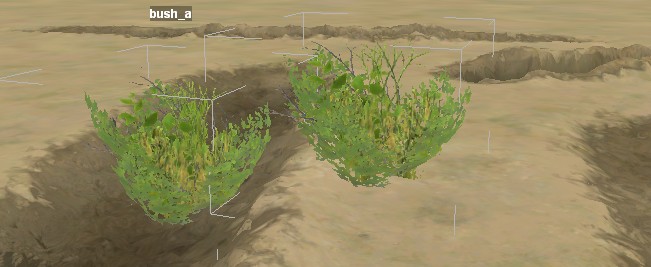
Mud ruts tend to look most realistic when drawn with the smallest brush sizes and with moderate values. Draw them in pairs to emulate ruts from one truck, or draw many parallel ruts to emulate a well traveled path. The Autofade checkbox can be used to ease the rut into existence so that it doesn’t have sharp ends.
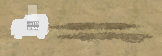
Erase Mud
For mud that was created with the Extrudes brush, either brush can be used to reduce the depth and softness of the mud by painting with a value less than 0.5.
For mud that was created with the Automatic brush, neither brush does a satisfactory job of reducing the mud. The Extrudes brush reduces the depth and softness of the mud without reducing the visual effect. This may cause the ground to intrude on the mud coloration, which looks weird. On the other hand, the Automatic brush reduces the mud coloration much more quickly than it reduces the softness of the mud or the visual depth of the ruts. This can result in visual ruts that are not mud colored and which a truck simply floats over.
For these reasons, it is often more effective to simply erase all of the mud in an area and start over than to try to correct mistakes. Either brush can be used with a value of 0.0 to quickly eliminate all mud and associated visual effects. All visual effects are automatically removed when the mud is gone. Be careful to turn off Autofade when erasing with a large brush, or the eraser tails could end up accidentally removing mud very far away.
As with other terrain tools, the “Undo All” button undoes any editing that you did during the current invocation of the tool. However, although the brush window has a “Backups” button just like the other terrain tools, the editor does not automatically create backups of the mud file. You can always open the map’s bitmap directory and make a copy of the “mud” file by hand. If the mud file is not present, then the map has no mud.
More Information
Pavel Zagrebelnyy, the lead MudRunner developer, has written an article about the mud system in MudRunner.
Create a Locator
The locator object is used to create a garage, fuel station, log station, lumber mill, watchpoint, random truck, or teleport point.
Create a Locator
Right click anywhere in the main view and select “Add Locator”. A locator will appear in the middle of the view. The locator is represented abstractly as a long arrow with a short arrow pointing 90° right of the long arrow.
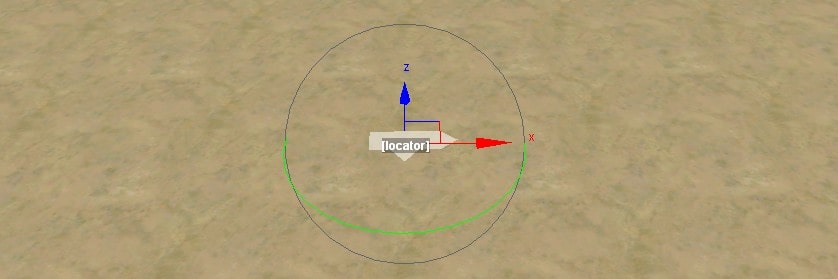
As with trucks, a locator cannot be selected directly from the main view. You can only select it by left clicking it in the Scene View.
A locator is always attached to the ground, so it records only a 2-D position and 2-D orientation, and its interface is stripped down to match. You can move the locator in the X and Z planes (or both at once), and you can rotate the locator in the ground plane.
Resize the Locator
The locator initially starts with zero width and length. Set its dimensions by typing values directly into its properties. A rectangle with the specified length and width is centered on the locator. The long arrow of the locator points in the direction of its length, and the short arrow points in the direction of its width. (Which dimension is length and which dimension is length generally doesn’t matter, though.)
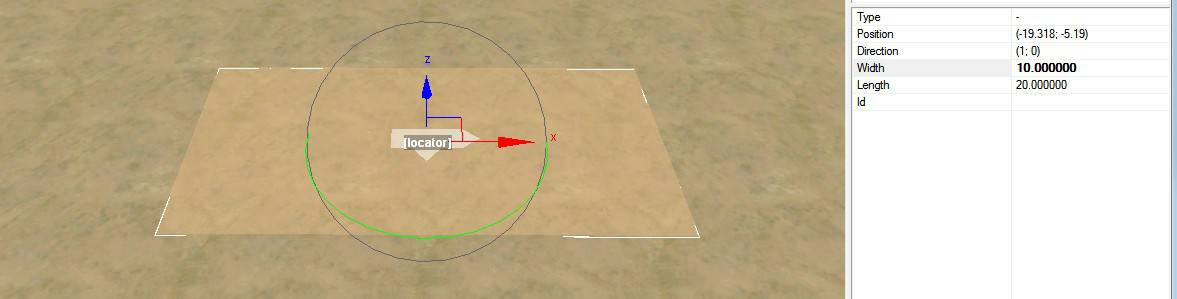
If the locator isn’t on flat terrain, the editor (and the game) will outline the locator from wherever the corners of the rectangle lie on the terrain*. As long as the center of the player’s truck is somewhere within the 2-D space of the rectangle (regardless of height), she can access the locator’s function. However, it generally looks better if the ground is smoothed flat (if not necessarily level) within the bounds of the locator.
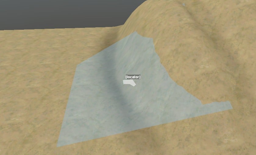
(*) The game creates a rectangle 1 meter longer and wider than what is displayed in the editor (each corner is 0.5 meters further from the center), and it uses the terrain height at those different corners accordingly.
Set the Locator Type
You can set the locator type by choosing it from the dropdown menu for the Type property. You can click in the Type property and press the key for the first letter in the locator type to quickly change the type (e.g. “g” for “garage”).
The various locator types are summarized below.
A garage allows the player to change the trailer and addons on her truck. It also repairs and refuels the player’s truck, but only up to 200 liters of fuel (and it won’t refill addons). In casual mode, the player can also recover her truck to the nearest unlocked garage. Recovering to a garage is described more below. If the center of the garage locator is within 64 meters of the active truck (twice as far as the drawn active radius), the garage is unlocked at the start of the map. Otherwise, the garage starts out as locked. In single player mode, the player must bring 4 garage points to a locked garage to unlock it. In multi-player, the players must bring 8 garage points to the garage to unlock it.
A fuel station allows the player to refuel her truck and all addons to completely full (no 200 liter limit). Fuel stations are always unlocked.
A log station supplies logs to the player in casual mode. In hardcore mode, the log station is not visible and doesn’t do anything. In hardcore mode, logs can only be supplied by the log kiosk. The log kiosk is a model rather than a locator; it is described in the “Special Models” section of this guide.
A lumber mill accepts logs toward completion of its objective. When all lumber mills have received their logs, the map is considered complete (although the player has the option to continue playing).
A watchpoint hides the map in a circle around it with a radius of 220 meters. The watchpoint radius is revealed in the main view after setting the locator type, then selecting something else to commit the change, then selecting the watchpoint again. (The width, length, and rotation of a watchpoint don’t matter and don’t need to be set.) The hidden region is revealed when the player approaches within 10 meters of the watchpoint to unlock it. The watchpoint cloaks map features and locked trucks, but not locators or log kiosks. A scavenge point is not hidden by a watchpoint, but whether it has logs is hidden until the player uncloaks the watchpoint or approaches the scavenge point to explore it.
If two or more watchpoints overlap the same region, each only unlocks the portion that is closest to it. (Roughly. It gets weird if the watchpoint centers are much closer than 200 meters from each other.)
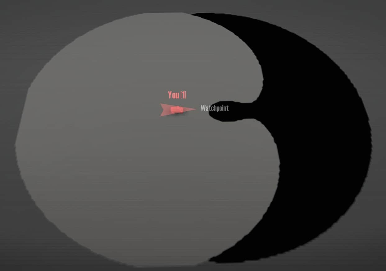
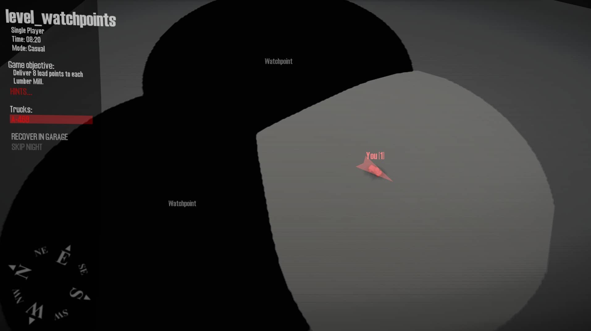
If no locator type is chosen, the locator acts as a teleport target in the proving ground only. While testing the level in the proving ground, you can click on the locator in the navigation map to teleport to that location. Your truck will be facing in the direction of the shorter locator arrow. You can type a string in the locator’s Id property to give the teleport point a name on the navigation map. The Id property is otherwise unused for all other locator types. A locator with no type is typically ignored in a published map, although a game mod might make use of it. The width and length of the locator don’t matter.
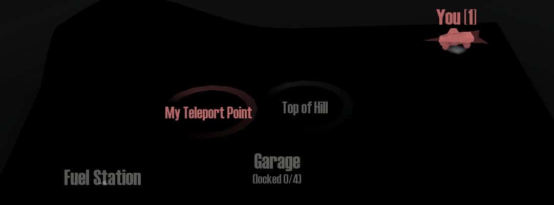
Avoid Locator Overlap
If two locators overlap, the player can only use one of the locators in the overlapping region. The same occurs if a locator overlaps a log kiosk. Avoid these overlaps to avoid confusing the player.
Recover to a Garage
In casual mode, the player can recover her truck to the nearest unlocked garage, where normally it is repaired and refueled. However, the game has a bug so that it swaps the garage locator’s length and width when calculating a place to position the truck. This means that the truck may recover to a location outside the actual locator rectangle. When using a rectangular garage locator, make sure that there are no obstacles within the area that would be under the rectangle when rotated 90°. However, the player may still end up frustrated if a truck that is broken or out of fuel ends up outside the garage area. I recommend a square garage locator to avoid the bug entirely.
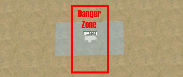
When the player recovers her truck to the garage, it appears entirely within the rectangle and facing in the direction of the shorter locator arrow. The game searches for the first available position that does not overlap another truck, starting in the corner behind both locator arrows.
The recovered truck facing may change if the developers fix the rectangle orientation bug. To be safe, the garage locator should be at least 8 by 8 meters to fit any truck at either major angle. If the garage locator isn’t big enough (or if too many trucks are blocking the available area), the game will simply ignore the player’s requests to recover to the garage.
The search for a safe truck location only checks against the positions of other trucks. It does not check for models, plants, etc. Therefore, the entire garage locator region (and the danger zone for a rectangular garage) should be free of obstacles to avoid a physics catastrophe.
The recovered truck loses its trailer, any logs the truck is carrying, and any fuel in the truck’s addons. Repair points are also lost during the recovery, but as long as the truck lands safely within the unlocked garage, they will immediately be replenished.
Edit Material
When a new map is created, it uses a grass_to_dirt material for all terrain. Open the Materials category in the Scene View and click on the grass_to_dirt material to access the material tool.
Edit Material Elements
The properties panel shows that the material has two elements, grass and dirt. These elements are the defaults for the “Grass” property and the “Dirt” property. These properties are poorly named because any element can be chosen for each, and so I will always refer to them in quotes as a reminder of their unusual nature. To choose a different element, click on the “[press]” text next to “Choose Grass” or “Choose Dirt”. A window appears showing examples of all terrain elements from which you can choose. If you change either element, the name of the material will update accordingly in the Scene View.
By default, the base material is drawn entirely with whatever element is chosen for the “Dirt” property. When the material is selected, you can paint either the “Grass” or “Dirt” onto the terrain using the brush. Brush values less than 0.5 paint with “Grass”, and values greater than 0.5 paint with “Dirt”. If the brush is applied only softly, the terrain is painted using a blend of the two elements.
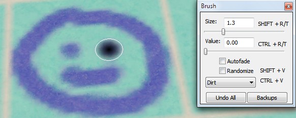
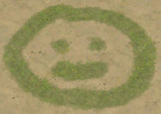
Each material element includes a ground texture and may also include 3-D grass or dirt clods on the surface. When you use the material brush, the editor updates the ground texture right away. But to update the 3-D effects, you’ll need to select “Rebuild Terrain” from the context menu.
Some materials may prevent certain plants from being distributed on the material. Distributions are described in the next section. A reference guide to the material elements can be found elsewhere in this guide. Among other things, it includes information about which plants are automatically included by each material and which plants are excluded by each material.
Add a New Material
You can add a new material with a different pair of elements. Select “Add Material” from the context menu.
Every new material must be assigned an associated bitmap file in its Map property. By default, this is “mtrl_new.tga”, but you really should change this or else your various materials will end up using the same file and conflicting with each other. You cannot directly type a new file name. Instead, when you click on the property, an ellipsis (“…”) appears to the right of the file name. Click this to open a file chooser. For a new material, presumably you won’t be selecting an existing file. Instead, just type the new file name into the file chooser. The file must be in your map’s bitmap directory, and the file name must be in the form “mtrl_[name].tga”.
Each terrain block can display only one material with its two associated elements. To use a material in a terrain block, you must set it to be opaque (visible). To make the material opaque, press ctrl-V to switch the brush from “Dirt” to “Opaque”, then paint one or more terrain blocks with a value greater than 0.5. To return a material to transparent for a terrain block, paint it with a value of 0.5 or less. If any part of the brush touches a terrain block while painting, the opaqueness of the entire terrain block is updated.
To return to drawing with the “Grass” or “Dirt” elements, press ctrl-V to switch back to the “Dirt” brush.
Opacity is recorded in the TGA file and displayed in the material tool using the blue channel, and “Dirt” is recorded and displayed using the green channel. These two colors combine as follows:
- Cyan (blue-green) is opaque and displays the “Dirt” element.
- Blue is opaque and displays the “Grass” element.
- Green is transparent, but would display the “Dirt” element if made opaque.
- No color is also transparent, but would display the “Grass” element if made opaque.
These colors are overlaid over the terrain while using the material tool, so the colors may be modified somewhat by the underlying terrain color.
When a new material file is chosen, the editor creates it filled with green (“Dirt”) along with a grid in the red channel (which appears yellow when combined with the green “Dirt”). The red channel has no visible effect on the map outside the material tool.
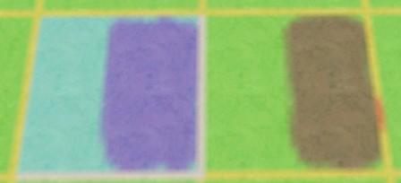
If multiple materials are opaque for the same terrain block, only the last opaque material is used (based on the order in which they appear in the Scene View). If you’ve made a material opaque for a terrain block, but it isn’t showing up, check for conflicting materials that are also opaque for that block.
If no materials are opaque for a terrain block, the first material is used (usually mtrl_base.tga).
Blend between Materials
When materials with different elements meet at the edge of a terrain block, there is no smooth blending between the two. Instead, there is an unnatural looking edge. To avoid this, it is best for the adjacent materials to each have an element in common which is used along the shared edge.
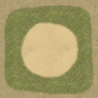
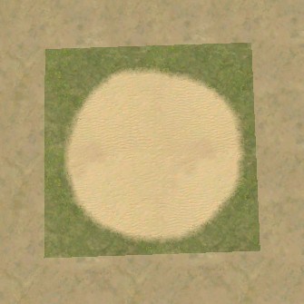
Delete a Material
You can right click on a material in the Scene View to get a context menu where you can delete the material. If you like to keep a clean directory, you can also manually delete the associated TGA file.
Create a Distribution
Plants (and debris) can be quickly created in large quantities using distributions. To create a new distribution, select “Add Distribution” from the context menu.
Every new distribution must be assigned an associated bitmap file in its Map property. You cannot directly type a file name. Instead, when you click on the property, an ellipsis (“…”) appears to the right of the file name. Click this to open a file chooser. For a new distribution, presumably you won’t be selecting an existing file. Instead, just type the new file name into the file chooser. The file must be in your map’s bitmap directory, and the file name must be in the form “dstr_[name].tga”.
Choose Plants
Choose what plants will be in the distribution by clicking “[press]” next to the Edit property in the Brushes category. A window will appear allowing you to choose as many distribution brushes as you desire.
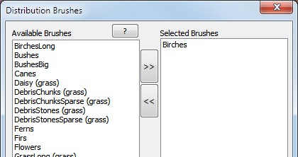
Move a brush from the left “Available Brushes” column to the right “Selected Brushes” column by clicking its name and then the “>>” button. Move it back by selecting it from the right column and clicking “<<“. Or quickly change a brush from one side to the other by double clicking it in either column.
Each brush includes one or more plant types to be included in the distribution. Reference information for the distribution brushes appears elsewhere in this guide.
Drawing the Distribution Region
Once you have chosen one or more brushes, use the distribution tool’s “Density” function to increase the density for the chosen plants where desired on the map. Density is drawn using the red channel.
It is not unusual to draw most regions with 100% density, which actually corresponds to “100% of typical density”. You can draw with lighter density to distribute plants more sparsely than typical.
You can also switch the brush to the “Scale” function to change the scale of plants in the distribution. By default, the scale is randomized across the entire range of possible values. However, you can bias the scale of your distribution by drawing different scale values onto the map. Scale is drawn using the green channel. To restore the scale to its fully random range, draw with the “Randomize” checkbox enabled and the Value set to 1.
The editor will not always draw your newly distributed plants in the main view when you exit the distribution tool, or it will only draw them in the visible terrain blocks. Right click the main view and select “Rebuild Terrain” to fully redraw.
After distributing plants onto the map, you can go back and edit your distribution by changing what plants are part of the distribution and/or drawing or erasing different areas. This flexibility allows you to very quickly and easily distribute plants across the landscape in a natural looking fashion.
Plant Density Restrictions
Although you can distribute many different plant types in the same area via distributions, the editor will generally limit the total density of plants in each of a few categories such as big trees, small trees, grass, and debris. Thus, by choosing many different plants to distribute, the frequency of each plant will often be reduced. The “Distribution Reference” section has more information on these density conflicts.
The order of distributions and the order of brushes within a distribution influences how many plants each brush gets to distribute. The first distribution and the first brush in a distribution have the first distribution opportunity. The remaining brushes and distributions can only place plants where they can find an appropriate gap (if any).
There are a few plants (such as mushrooms) which default to a low density even when the distribution is drawn with maximum density. For these cases, overlaying a second distribution with the same plant can increase the overall density. For most large plants, however, using the same plant in multiple distributions will result in little or no increase in density.
Besides avoiding other distributed plants, distributions avoid distributing plants near individually placed plants in the same category. So you can manually place plants as needed in critical locations (e.g. as winch points), and the randomly distributed plants will smoothly fill in around them.
Random Seed
Plants are distributed randomly up to the mapped density. (There’s no reason to use the Randomize checkbox for density because it will just decrease the average density.) Since the random distribution is not drawn and is therefore out of your control, the editor seeds the random function with a fixed value which you can control. This value is kept in the Seed property.
If you don’t like the random placement of plants in the distribution, you can choose a different seed value. You might do this, for example, if the random distribution has an unusual gap in a highly visible location. Different seed values will not help you if your density bitmap isn’t quite right, however. In most cases, the best way to fix the distribution is to draw a larger region of maximum density to get more plants, or carve out a region of zero density where plants are undesired.
Be aware that even with a fixed seed, any changes to the drawn distribution region or to other distributions may cause a different random placement of plants. Plan to review the critical borders of your distributions for misplaced plants before publishing.
Ignore Water, Overlays, and Mud
By default, plants are not distributed in water, on a road, or in mud. However, you can tell the distribution to ignore the water, road (overlay), or mud and distribute the plants at that location anyway.
You may occasionally see plants being drawn in water, on a road, or in mud even when these checkboxes are not checked. This often occurs because the editor has drawn the distribution quickly and sloppily. To fix it, choose “Rebuild Terrain” from the context menu.
Create a Road
A road is a kind of overlay, so called because it overlays the underlying terrain. To create a road, right click in the main view and select “Add Overlay”. A window appears showing the various overlay types. Click on an overlay and click “OK”, or double click an overlay to immediately choose it.
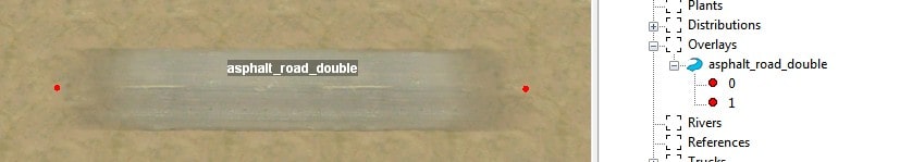
Once the overlay type is chosen, you can type a new value into the Type field, but I do not recommend it. If you mistype, the editor may get confused or crash.
The road is created with two points, labeled 0 and 1. Each point can be individually selected and moved. More points can be added to the road, and the editor will draw the road as a smooth curve between them.
To select a point, click on it in the main view, or expand the road overlay in the scene view and click one of its numbered points within. If the point is off the edge of the map, you can only select it from the Scene View, not the main view.
A point can be moved using the standard interface. While moving one or more points on the road, the editor does not redraw the entire scene, but just draws the new road position in pale blue. To redraw the road at its new position, deselect the road, or select “Update” from the context menu.
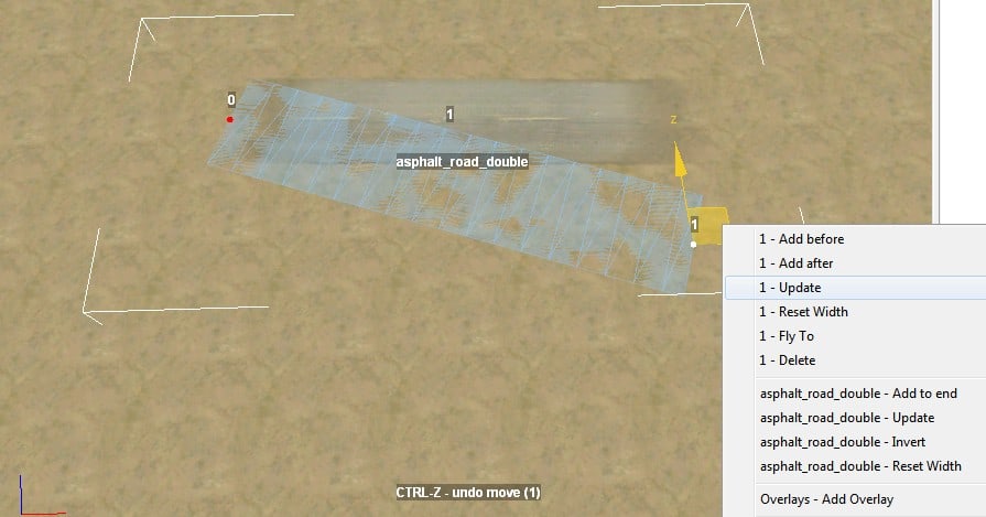
“Update” actually appears on the context menu twice. This is because the context menu includes contextual items for both the selected point and its parent road. Update for either the point or the road does the same thing.
The ends of the road fade out smoothly for about the last 4 meters, allowing you to blend in mud or other techniques to make a natural looking transition to wilderness.
Add a Point
The context menu also allows you to add a new point to the road. Whenever a new point is created, it is automatically selected.
“Add to end” creates a new point after the highest numbered point on the road so far. The editor looks at the distance between the last two points on the road so far and creates the new point half that distance away.
If the last point on the road is currently selected, “Add after” does the same thing as “Add to end”. But if some other point is selected, “Add after” creates a new point midway between the currently selected point and the next one.
“Add before” similarly creates a new point before point 0 or creates a new point midway between the currently selected point and the previous one.
If you prefer the road to be numbered in the opposite direction, select “Invert” from the context menu.
A new point is numbered so that it has the correct order with respect to the other points on the road. However, it is always added to the end of the list of points in the Scene View, regardless of its order on the road and numerical order. This can be confusing. The order of points in the Scene View is corrected if you save and reload the map or if you invert the road twice.
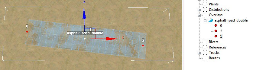
Delete a Point or a Road
To delete a point, select it and choose “Delete” from the context menu. Be careful deleting down to only 0 or 1 point. The editor will display an error and may crash.
To delete an entire road, select the road in the Scene View and choose “Delete” from the context menu. To avoid accidents, the editor does not include the Delete option in the road’s portion of the context menu when an individual point is selected.
Road Dropouts
The game engine doesn’t have a clean way to merge road overlays together. Instead, if any part of a road overlay is too close to another road of the same type, the road simply fades away. You can patch this missing road sections using a material (such as concrete) that roughly matches the color of the road, or you can hide it with mud or other effects.
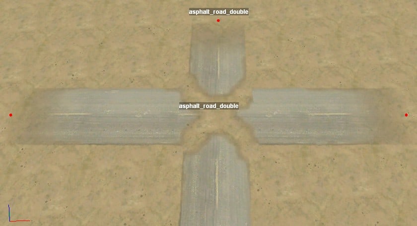
If your road includes a tight curve, then the points on the inside of the curve end up too close together, which triggers the same fading effect. You can fix this by relaxing the curve or by patching it as above.
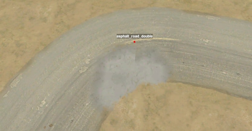
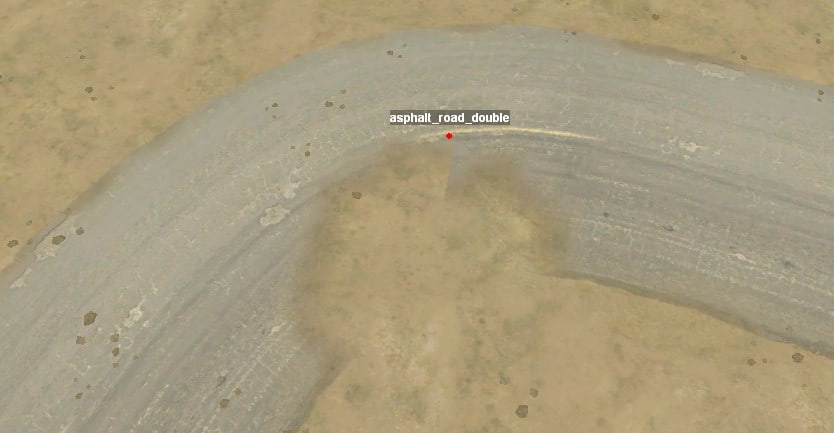
You will probably find yourself spending a lot of time fixing road intersections.
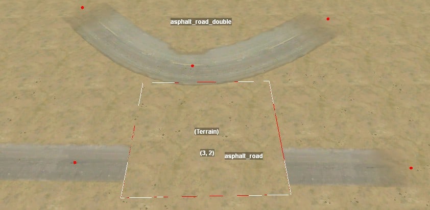
The navigation map (previewed in the “Terrain Game Map” panel has no problem with drawing intersecting roads. However, it draws them with the first roads on the bottom and the last roads on the top, regardless of their drawing priority in the game engine. When you are done with roads, you may wish to hand edit the XML file to put them in the desired drawing order.
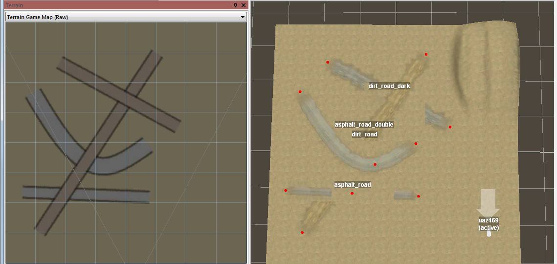
Road Width
Each type of road has a default width. For asphalt roads, this width cannot be changed. For other road types, the width can be changed for each point. To change the width of the road at a point, select the point and drag up or down from the diamond around the point. Or type a new width directly into the point’s Width property.
For widths less than the default, part of the road texture is dropped at the edges of the road. For widths greater than the default, the road texture is duplicated to extend the edges of the road. This may look particularly unnatural for some road types.
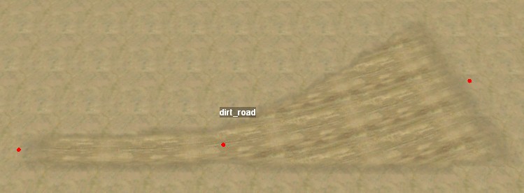
You can reset the width of the road to the default value in the context menu. If you select the “Reset width” option for the numbered point, only that point is reset. If you select the “Reset width” option for the road, all points on the road are reset.
Other Road Properties
Flatten
The “Flatten” property of the entire road will flatten that road across its width when set to True. The flatten effect fades out at each end of the road in the same way that the road texture fades.
The flatten effect does not affect the dirt_path and similar primitive roads. Which roads ignore the Flatten property is listed in the Road Reference section.
The flatten effect is applied without changing the recorded terrain geometry, so you can experiment with flattening without destroying your terrain. (You may need to Rebuild Terrain to make your changes visible.) Trying to adjust the terrain height below a flattened road can be very confusing, however, so it’s best to set the Flatten property to false before working on the terrain geometry.
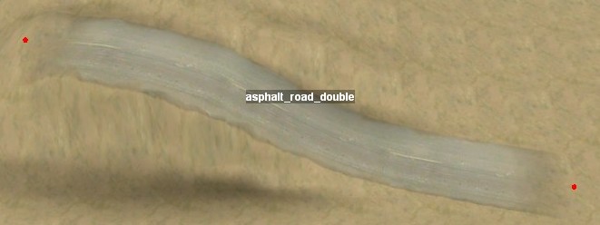
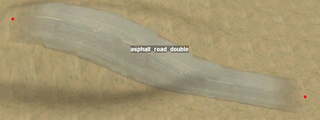
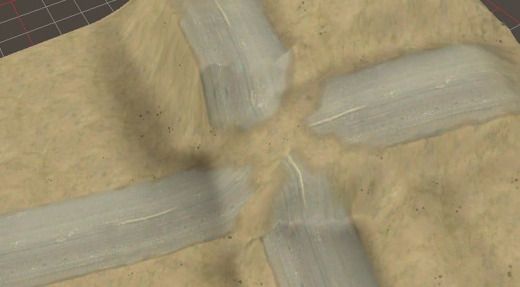
Although the road is flattened from side to side, the game engine does nothing to smooth the road along its length. For this reason, it’s a good idea to apply a terrain smoothing pass along the length of the road as described in the “Edit Terrain Height”. If you then enable Flatten for the road, it will remove any residual road tilt that could annoy the player.
ApplyOffset
If ApplyOffset is its default value of “true”, the editor applies pre-defined bumps and ruts to the road based on its the road type. The pre-defined bumps are described in the Road Reference section. Changing ApplyOffset to “false” prevents thes bumps. Rebuild Terrain is required after changing the value.
The offset is applied without consideration of the “one road type per terrain block”. I.e. ruts may continue where the road is not visible. Where roads intersect, the offset is applied for the last road listed in the Scene View, regardless of priority.
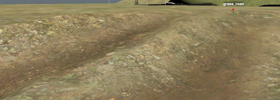
Lampposts
Lampposts can be automatically added to a road by clicking “[press]” for the Edit property under the Brushes category for the road.
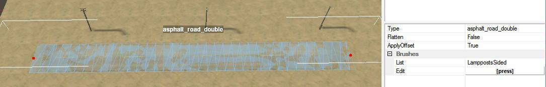
CityLamps use bright white lights. Lampposts and LamppostsSided use dimmer lights with a random mix of white and yellow (sodium) bulbs.
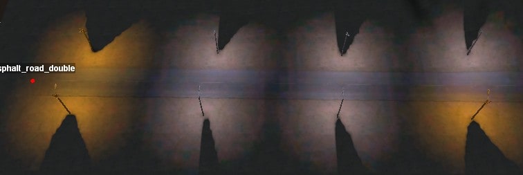
“CityLamps” and “Lampposts” are only on one side of the road. If facing the road with low numbered road points on the left and higher numbered ones on the right, the lampposts are on the far side of the road. Invert the road direction to cause the lampposts to switch sides.
Multiple types of lamps can be added to one road, but doing so causes them to be drawn on top of each other.
Each lamp type is always a fixed distance from the road centerline, regardless of the road width.
Type
As with the Brand property for plants, the Type property for roads (and other overlays) is directly editable, but it is your own responsibility to choose a correct new type.
Create Other Overlays
Other overlays can be created in your map. Any number of these non-road overlays can be created in the same terrain block, and the game engine is able to draw them overlapping each other or roads.
The Flatten and ApplyOffset properties have no effect on these non-road overlays. However, you can add lamp brushes to the non-road overlays if you really want to.
Wires
Unlike the curves of other overlays, wires (pole_wires) travel straight from point to point. When moving a wire point close to a pole, the point will snap to the pole’s coordinates. This allows you to quickly wire up the lampposts along a road or any pole models that you have indvidually placed.
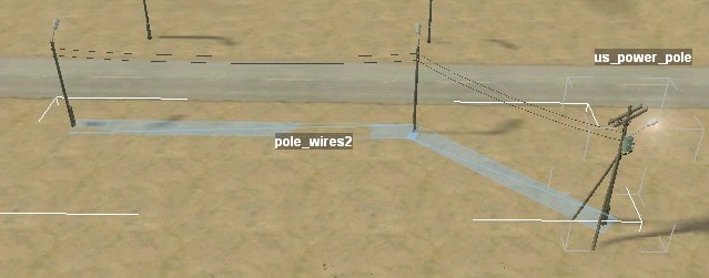
Note that wires do not actually attach to a pole; they merely snap to the pole’s location. If you move the pole, the wires will be left behind.
Because wires float in the air and their points are not highlighted, it can be difficult to select them in the main view. You can instead select them in the Scene View.
Road Borders
The asphalt_border overlay is a low curb that you can lay along the edge of a road or concrete patch. The highway_border overlay is a higher guardrail, although it isn’t tall enough to prevent a determined player from driving a large truck over it. To have the guardrail face toward you, orient it with low numbers on the left and high numbers on the right when facing the guardrail from the road.
Each of these types of road borders sinks into the ground at each end and includes however many fixed-length segments in the middle as are needed. For the guardrail overlay in particular, the middle segments are quite long, which means that the final sinking piece is not always placed as desired near the last overlay point. Usually you fix this by adjust the points slightly to change the total guardrail length until the final piece is placed as desired. The long segment lengths also mean that you may need to make the spline longer for any segments to show up at all.
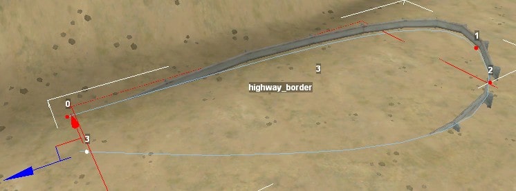
Cliff
A few styles of cliff are available. Each of these consists of a curved spline with no defined width.
The line is intended to be draped along the top of the cliff, where it creates a distinct top lip for the cliff. Some of them include different materials for the top edge vs. the cliff face, so you’ll want to update your material selection to match.
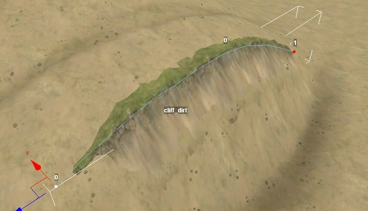
When facing the cliff from below, the cliff overlay should be laid out with 0 on the left and the highest number on right. Otherwise the overlay will be upside down. Use the “invert” item on the context menu to invert the point numbers and thus also the cliff orientation.
Roots
A recurring series of roots can be drawn over the terrain using the roots overlay.
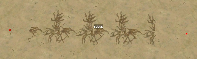
Create a River
All water in MudRunner is in the form of rivers. Of course, you can also make a “river” with stagnant water in an enclosed hole to represent a puddle.
A river is much like a road overlay except instead of being draped across the terrain, each point of a river has a height.
Create a river by selecting “Add River” from the context menu. The river is created stretching from left to right across the center of the main view, and its height is the approximate average height of the terrain. So if you’ve already dug a trench for the river (or hole for a puddle), the river will be roughly the right height.
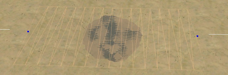
Rivers are easiest to create on flat or nearly flat terrain. (Or at least, the river surface should be close to flat.) The game engine draws steep rivers very poorly. Vertical waterfalls are impossible, although steep cascades can be created under controlled conditions.
I find it easiest to tint the terrain along the desired path first as a guide, then lower the terrain along the river channel, and finally add the river. After adjusting the height of the river points, I can then find any points where the height of the terrain needs to be further adjusted. (The edges of the map often require extra care since you can’t drag the height brush all the way across the edge.)
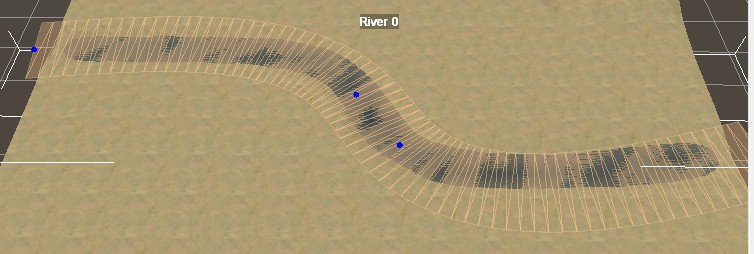
In general, you want the river to be wider than the river channel. Adjust the width at each point accordingly. The river is hidden where the terrain is higher than the river surface, which is what you want at the river edges.
The game engine handles sharp corners well, although there’s not much it can do to make a fast-flowing river look natural if the water bends back on itself.
You can make the river arbitrarily wide, but if the terrain is lower elsewhere, the river may start to intrude where you don’t want it. Be aware also that if river water is close under the ground surface, a truck will make splashing noises as it drives over it.
River Flow
The river has a Flow property. As far as I can tell, this does nothing. Instead, the speed of the river can be adjusted for any location along the river using the “(Water)” tool under “(Geometry)” in the Scene View.
The water tool has two brushes, Foam (drawn in the green channel) and Speed (drawn in blue). Paint any fast-flowing sections of river with the Speed brush (1.0 is faster) , and paint turbulent sections with the Foam brush (1.0 is foamier). The resolution of the water tool is a bit higher than the other bitmap tools for fine control: 31 pixels for every 16 meters.
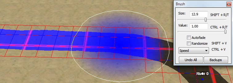
The direction of flow is from the low-numbered points to the higher numbered points. If you find that your river is flowing the wrong direction, choose “Invert” from the context menu to renumber it. Between points, the water flows parallel to the spline curve. Adjust your river points so that the flow is parallel to the riverbanks as much as possible.
The game engine renders high-speed water with waves and motion. The speed is quite obvious when it is animated and harder to see in a screenshot, but the fast water flowing into the still section should be apparent in the screenshot below.
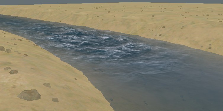
In addition to its visual effect, the speed of the river also influences how strongly it pushes against the player’s truck.
The Foam brush adds white air bubbles to the river surface and looks best in high speed areas.
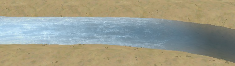
If foam is placed in a low-speed area, the water tends to roil as if it is boiling. This looks weird in large areas of still water, but can be OK for small areas around river obstacles.
River Mud
Mud and silt in the river can be drawn using the “(Mud)” tool under “(Water)” under “(Geometry)”. I.e. Geometry→Water→Mud, which is very different from the land mud in Geometry→Mud.
Each river can have two water colors that the mud brush blends between. These colors are set in the river properties “Clean Type” (for low mud values) and “Muddy Type” (for high mud values). Each of these colors can be selected from among the following choices:
- blue: for clear water.
- brown: for muddy water.
- dark: for deep water.
- green: for stagnant water with algae growing in it.
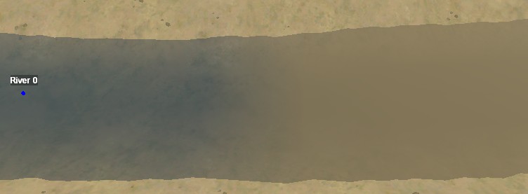
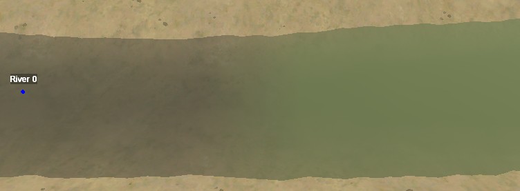
Steep Cascades
Creating steep watercourses is difficult for a number reasons. It can be tough to cut the right depth of channel into a slope of the terrain. It can be difficult to bend the vertical curves in the river just right to pour over the edge. But most of all, it is simply awkward to properly maneuver the river points in 3-D space while looking at a 2-D window. In particular, more points tend to be needed to keep the river in its channel, so its easy to have those points slightly out of line with each other, which can result in the river making odd shapes as its curve sharpens through the closely spaced points. Keeping all of the river points lined up is the best way to keep your river in the proper shape.
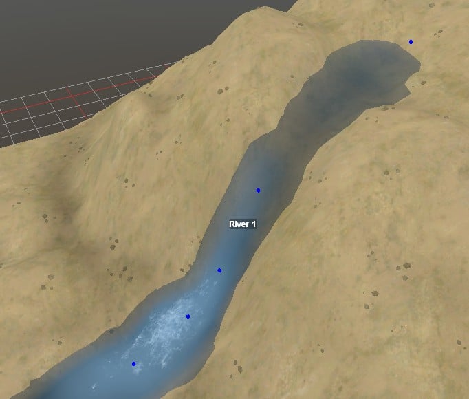
Note that where the river transitions between a steep area and a flat area, the river may bulge or dip as the game engine tries to smooth the transition. Try to control these bulges and dips to avoid the river flowing too obviously uphill through them.
River Junctions
Overlapping rivers combine quite well as long as they are the same height. The game engine averages the speed and direction of flow of the two rivers for the region of overlap, resulting in a natural looking junction. It can be useful to edit the Y coordinate of the river points manually to get as close a match as possible.
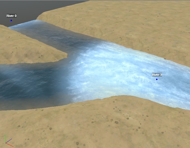
If merging rivers are different heights, the game engine does its best to smoothly merge their heights as well. This can result in small dips or swells in the river which are easily corrected if noticed. However, the game engine can also get quite confused, especially where more than two rivers meet at different heights.
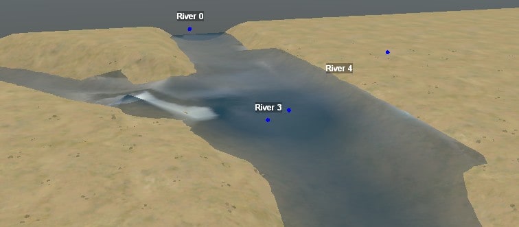
The problem becomes intractable where a flat river meets one at a steep angle. The game engine isn’t as good at averaging the different tilts of the rivers, and the results can look very unnatural. This can be puzzling to debug if one of the rivers is buried under the other. You might not expect them to influence each other, but they do.
The two screenshots below show the same two rivers merging. The left screenshot shows the desired configuration with one river cascading down a ridge and merging with another. However, if the lower river is too wide so that it includes area under the cascade, the result is a mess.
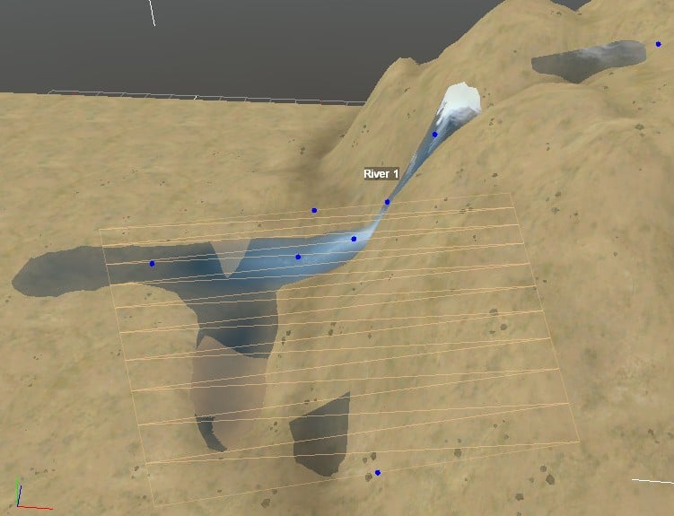
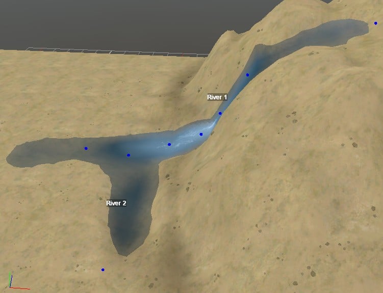
Only two mud colors can appear per terrain block. If two rivers merge, the mud colors of the lower numbered river are used in their shared terrain blocks. For a clean junction, at least one of their colors (Clean or Muddy) should match, and that should be the only color used across the terrain block boundary. Otherwise, a sharp edge in the water color will result.
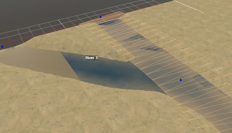
Add a Reference
Your map can import another map by reference. The imported map modifies the terrain height and (optionally) the terrain material, and it adds objects and overlays to the existing map features.
Use the context menu to Add Reference. A file chooser window appears, by default pointing to the editor’s prebuild directory of reference examples. Choose one of the map XML files here, or navigate to one of your own mod’s prebuild directories to include your own map XML file. (Don’t ask a map to reference itself, though. That way lies madness.)
If you selected one of the example XML files, the selected reference displays as a blank white rectangle the size of the referenced map. Move and rotate the rectangle as desired, then deselect it to commit your changes. If you Rebuild Terrain while the refence is selected, your changes to its properties are lost. If you Rebuild Terrain immediately after the refence is created, the editor has no committed properties to work with and only partially includes the refence.
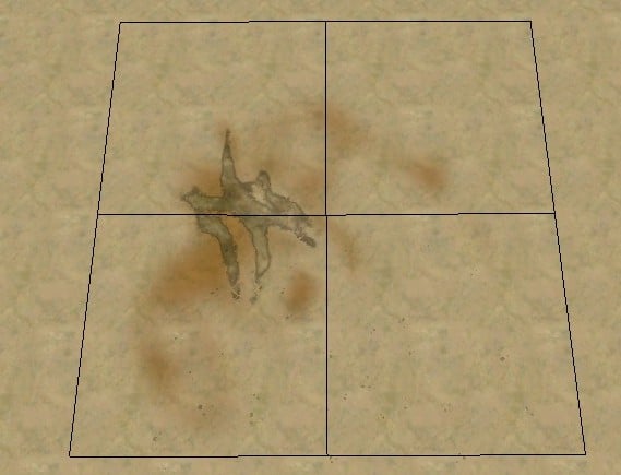
After deselecting the reference, choose Rebuild Terrain to redraw the terrain including all features from the reference. The reference examples don’t come with a compiled DDS file, so you will get a dialog box with an error message. You can just click OK, or first click the “Do not show again” checkbox to avoid getting the error every time you rebuild. The reference map will then be drawn inside your map.
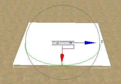
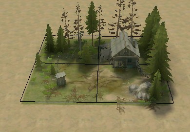
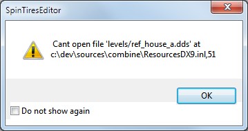

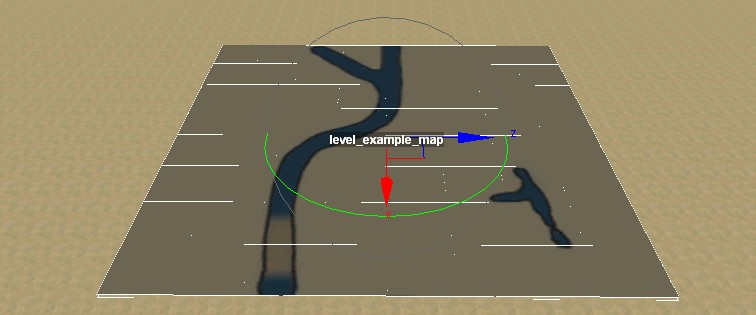
You can edit the position and orientation of the reference in either the main view or the Scene View. The position property displays a Y coordinate, but it doesn’t do anything. The orientation is displayed in the Scene View as a simple angle in degrees.
The name of the reference map is displayed in the STG property. This property cannot be edited.
Reference Height and Flatten Property
The reference map has its own base height relative to the default ground level (20.078 meters). When you include a reference map in your map, the average height of your map under the reference rectangle is added to the base height of the reference. If that portion of your map is flat, the included reference should fit smoothly into your terrain. If that portion of your map is hilly, however, the reference map will dramatically reshape the terrain.
By default, a “flatten” effect is applied to the region under the reference rectangle before adding the height of the reference. The editor then warps the inner edges of the rectangle in order to match the surrounding terrain.
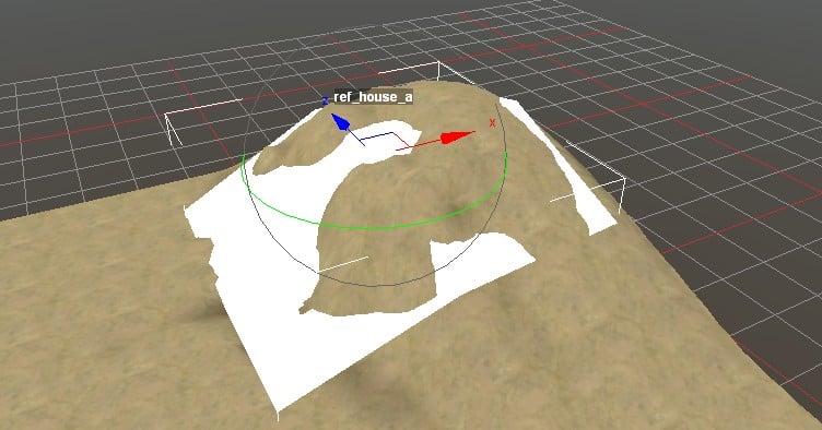
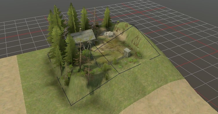
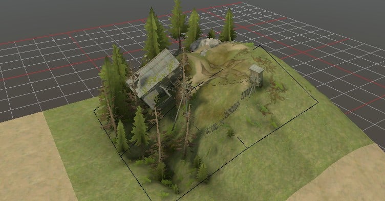
The terrain from your map ends up tilting the terrain in the reference. Models and individual plants in the reference are tilted by the same amount the terrain is tilted under them. (This occurs even if the model or plant is floating or buried.) Distributed plants simply follow their distribution rules on the new terrain (e.g. distributed trees tend to stay vertical).
Referenced Materials
By default, the materials from the imported reference have priority over your map materials for all terrain blocks touched by the refence. If you’d rather keep your map materials, set the ApplyMaterials property of the reference to false.
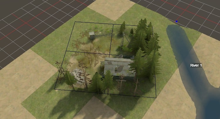
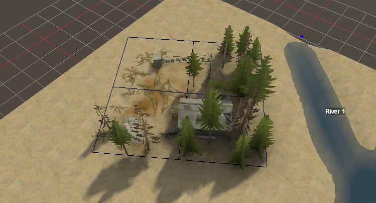
Objects that extend beyond the edge of the reference map are not cut off at the edge of the reference rectangle. Rivers and roads in particular can pose a challenge when they run to (and a bit beyond) the edge of the reference.
Reference River Colors
By default, the river colors from the imported reference are used in all terrain blocks touched by its river. Since a river can extend beyond the reference rectangle, the referenced river colors may be used in more terrain blocks than is obvious, especially if the river ends are hidden underground.
You can give priority to your own map’s river colors in your map by setting the AboveReferences property for your river to True.
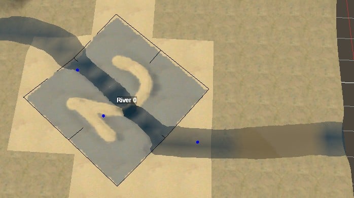
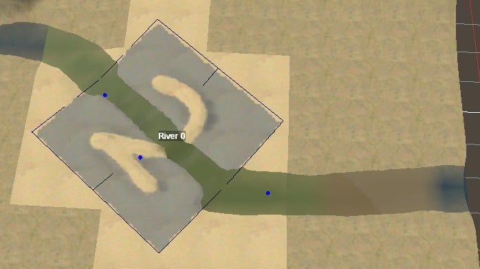
Besides the height, materials, and river colors described above, all other features from the reference map are merged with your map. Tint, mud, water speed and foam, and amounts of water mud are added together (capped at 100%). Locators from the reference map are added to the locators on your map, and the same is done for plants, distributions, overlays, and rivers. However, trucks are not copied from the reference map.
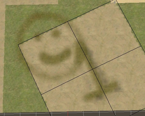
If roads are present in the reference map and in your map, they combine or collide the same as if they are all in your map. I.e. higher priority roads (from either source) suppress lower priority roads, and roads of the same type are merged together. For the purpose of drawing the navigation map, roads in the reference are treated as coming later in the Scene View and so are drawn on top.
Inter-Reference Conflicts
When two references overlap (or otherwise share a terrain block), both of their features are generally applied. However, some features such as the choice of materials can only come from one reference. The “Layer” property of each reference determines which reference wins these conflicts. Whichever reference has a higher number for its Layer wins. If they have the same layer value, the last reference as listed in the Scene View wins.
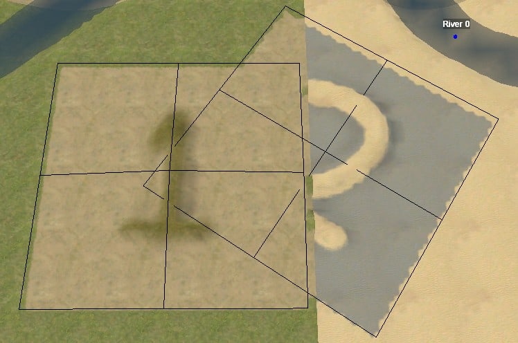
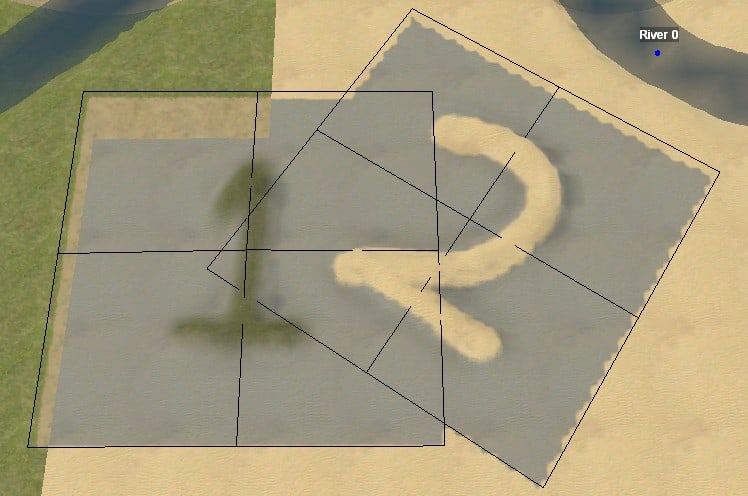
If you include a reference that itself includes references, the editor does not apply those subreferences.
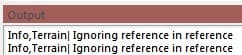
However, you can choose “Paste References from this Reference” from the context menu. This adds the referenced subreferences to your map with the appropriate position and orientation to match how they are used in the primary reference.
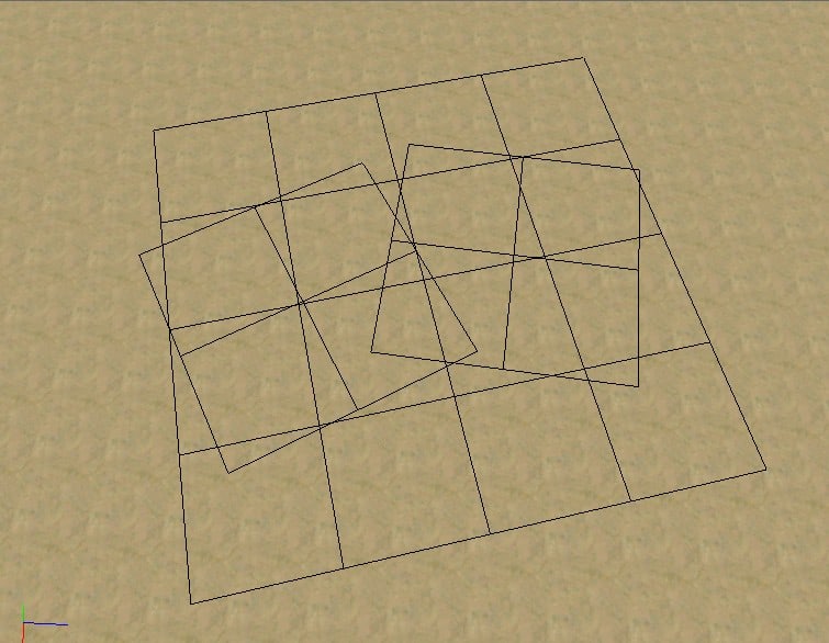
To remove the pasted subreferences, choose “Delete References from this Reference” from the context menu of the primary reference. Note that the editor does not actually track which references came from where. It simply deletes any reference whose center lies within the rectangle of the selected reference.
Create a Reference Map
Any map that you have created can be used as a reference.
If you create a map only to be used as a reference, it doesn’t need to be named starting with “level_”. The example reference maps start with “ref_”, which seems like a fine convention.
The reference map does not need to be in the same mod; the reference material is copied into the compiled files used by the game. If the reference map uses any custom classes, however, those need to be copied into your mod directory.
For best results, make sure that the edges of the reference map are at the default height (20.078 meters). Heights above or below that value will result in higher or lower elevation than the average terrain when imported into another map.
Be careful about putting objects near the edge of the map. They could get tilted when the height is warped to line up with the containing map. And of course, do not put objects beyond the edge of the map.
Rivers and overlays can pose a challenge if you want them to run to the edge of the reference map and merge with rivers and overlays in the containing map. You may choose to make a river or road extend just barely beyond the edge of the map (just enough so that doesn’t fade out prior to the edge). Or you may choose to leave it off of the reference map and rely on the containing map to create the river or road through the reference map.
Add a Route
You can add a route using the context menu for Routes in the Scene View. There is no “Add Route” option in the generic context menu.
Routes are a simple spline. I cannot get them to do anything in the game. My best guess is that routes are used by the game’s tutorial and challenges, and they require map-specific logic built into the game in order to function.
Scene and Terrain Properties
Scene Properties
Click on the top-level Scene category in the Scene View to see the one scene property: Time speed. Its value can be adjusted from 0 to 2. It affects the speed of time in the editor for animated effects such as river flow and wind in the trees. A value of 0 stops time. A value of 2 causes animations to move twice as fast as usual.
When the Time speed value is 0, the game engine stops drawing entirely. If you move the camera around, new terrain blocks are not drawn. If you Rebuild Terrain, everything disappears. Ha ha.
Pressing the “Pause” button in the top toolbar changes the Time speed value to 0. Pressing it again changes the value to 1, regardless of what it was before being paused.
The Time speed property only applies to the current MudRunner Editor session and isn’t saved anywhere.
Terrain Properties
Click on the “(Terrain)” category in the Scene View to see the map-wide properties that aren’t tied to any specific feature. This includes the number of terrain blocks in the map in the X and Z dimension. The map dimensions are set when the map is initialized and cannot be edited.
The (Terrain) category also has a Mutator property that allows you switch to a different set of media files from the original ones. This primarily effects textures, but some other files are also changed. The Mutator has the following possible values:
- (blank): the original media.
- Autumn: updated plants with fewer leaves and more yellow in the remaining leaves.
- USA: updated materials, mostly to add a reddish tinge to all dirt.
More information about the mutator options is in the Mutator Reference section of this guide.
After editing the Mutator value, Rebulid Terrain to redraw the map with the new value.
Rearrange the View Panes
The view panes in the editor window can be rearranged to suit your work environment. Panes can be resized, docked in various places, separated into their own windows, or hidden entirely. The arrangement of editor panes cannot be saved between sessions, however, so don’t invest too much in their rearrangement. In fact, you probably want to just skip this section.
Resize the View Panes
Drag the border between panes to resize them.
Drag the View Panes
The various view panes all share methods to move the panes around.
If you left click and drag the titlebar of any view, the editor will shift that view into its own window which you can drag to anywhere you like on your desktop. This is referred to as a “floating pane”. You can potentially drag all the panes out that way, leaving only the main view in the editor window.
While dragging the pane, icons will appear in the editor window near the center of each edge (top, bottom, left, and right). If you drag a pane so that the mouse is over one of these icons, a blue highlight will appear. If you release the mouse button at this time, the pane will reattach to the editor window in the highlighted position. While a pane is attached to the editor window, it is a “docked pane”.
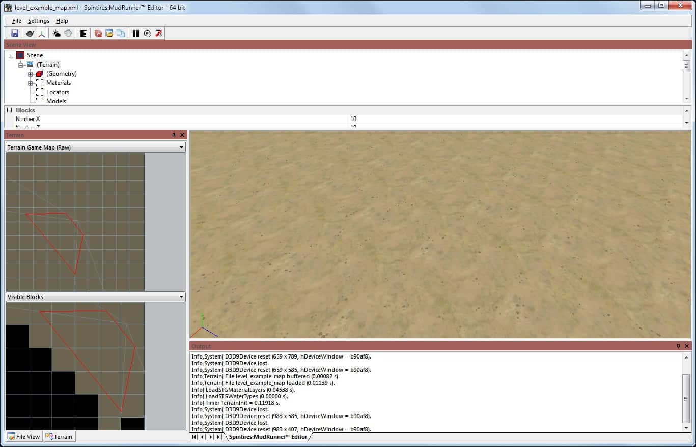
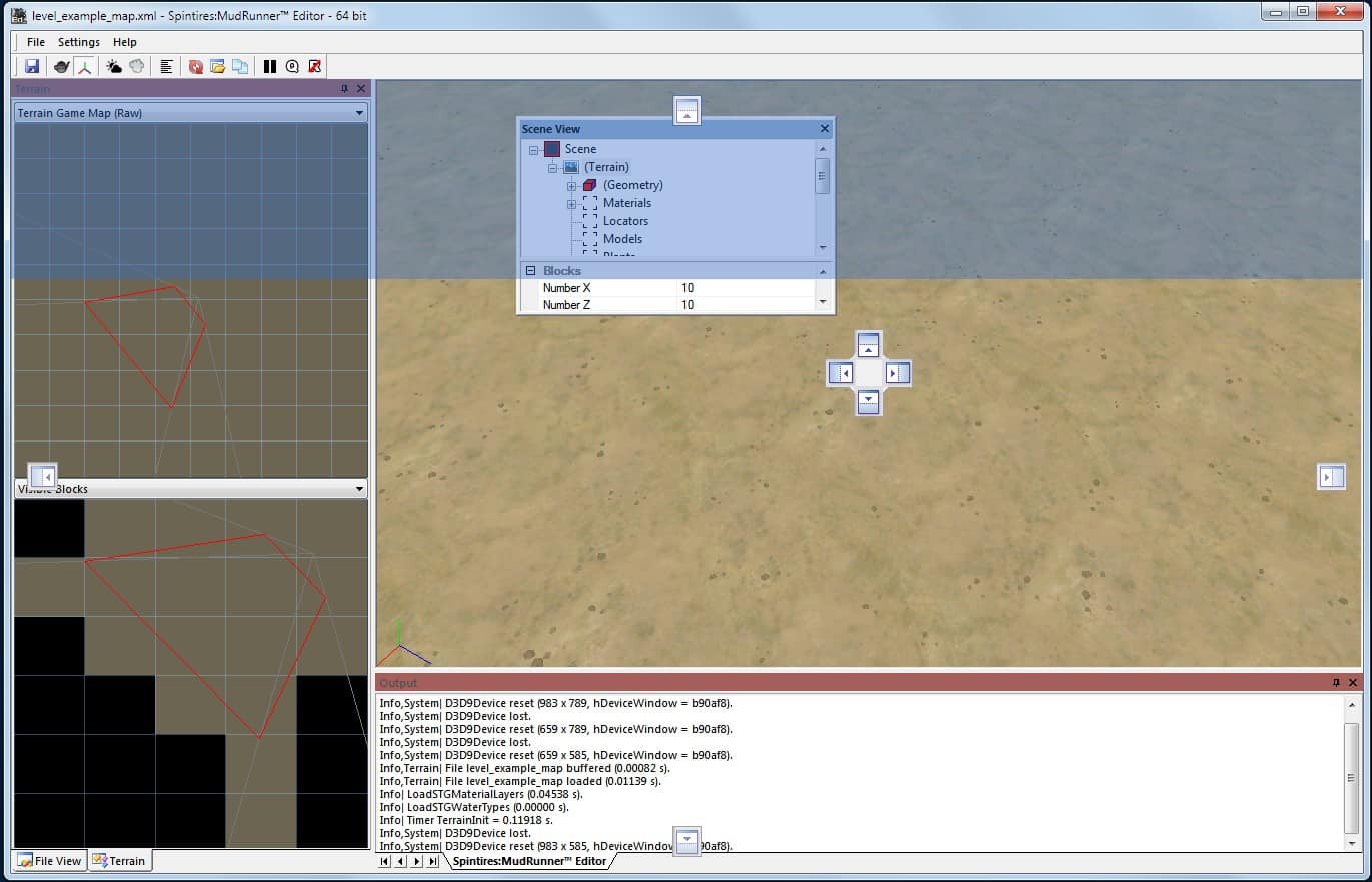
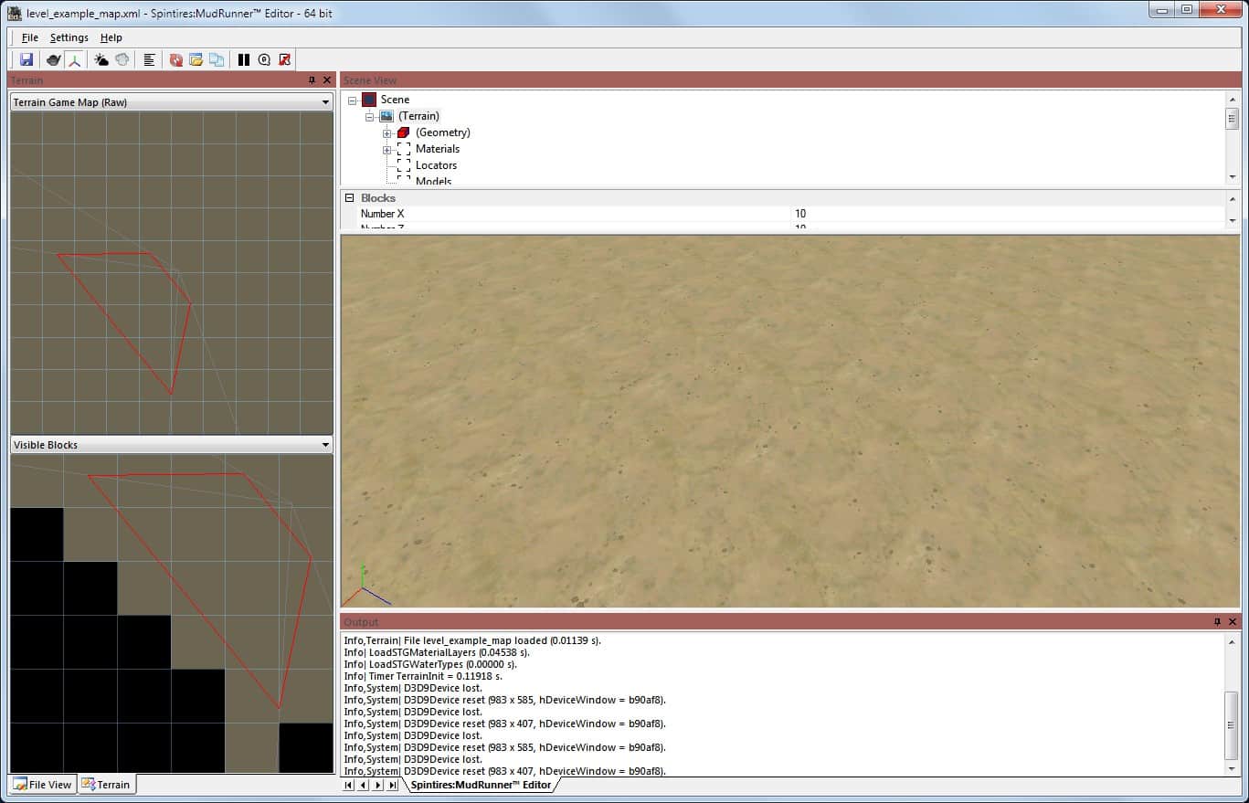
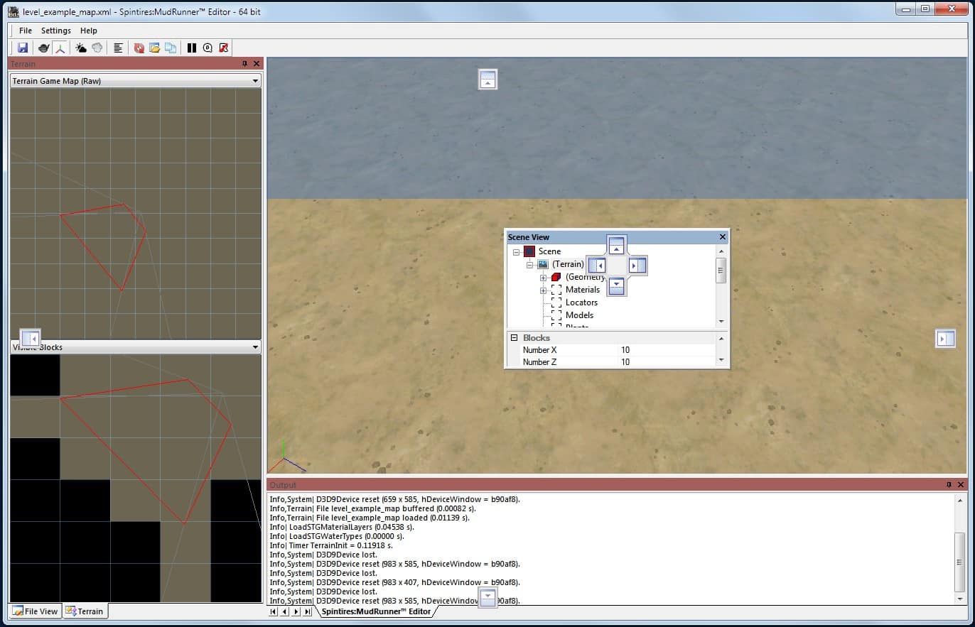
Release the mouse over the center icon to dock the pane as a new tab on the existing pane.
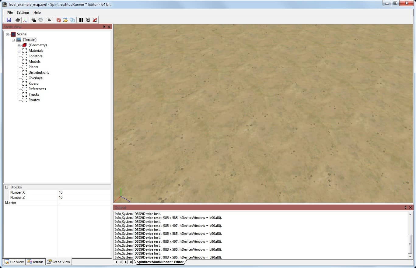
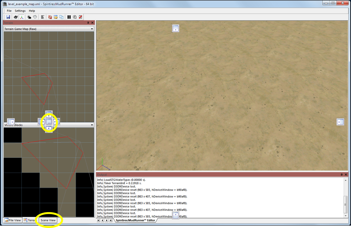
If you drag the titlebar of a tabbed pane, all tabs will be dragged with the pane. Alternatively, drag a tab at the bottom of the pane to drag only that view into its own pane.
Use the Pane Context Menu
Right click the titlebar of a pane to get a context menu for that pane. Or right click a tab at the bottom of a pane to get a context menu for only that view.
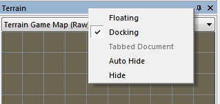
The top two items are mutually exclusive. If the pane is docked, select “Floating” to split it into its own window. If the pane is floating, select “Docking” to reattach it at its most recent docked position.
The “Tabbed Document” item in the context menu is always greyed out and does nothing.
The “Auto Hide” item collapses the pane into a different kind of tab on the edge of the editor window. Move the mouse over this tab to expand the pane. If you click the tab, the pane will stick around until you click on some other pane or outside the window. If you don’t click the tab, the pane will stick around only until you move the mouse outside the pane’s boundaries.
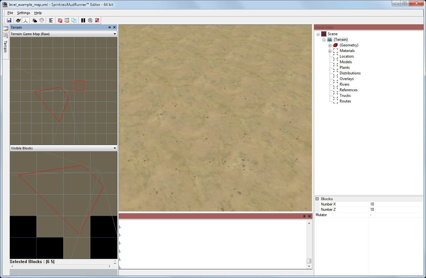
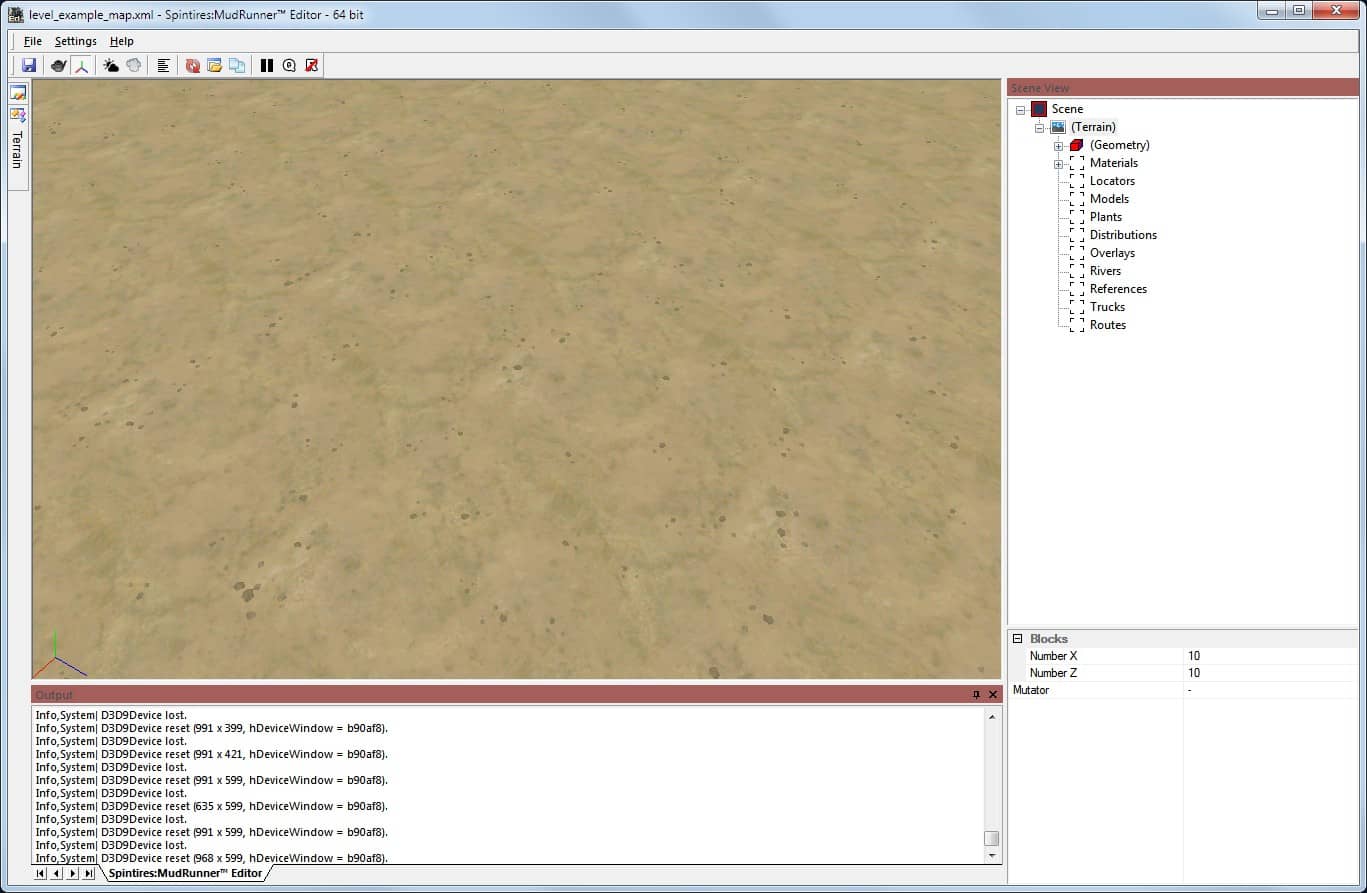
To disable auto-hide and display the pane normally, move the mouse over its tab to expose it, then right click its titlebar and re-select “Auto Hide” to restore it to its former docked position.
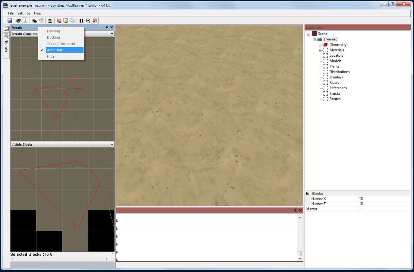
Auto Hide can also be enabled or disabled by left clicking the pin icon near the right side of the the pane’s titlebar.
The last option on the right-click context menu is “Hide”. It hides the chosen view. If the view is part of a tabbed pane, only that view is hidden, and the remaining tabs are still visible. A view can also be hidden by left clicking the X icon at the right side of its titlebar.
Warning: the only way to restore a hidden view is to exit and restart the editor application.
— Appendix A: Reference Information —
The following sections contain reference information for the various categories of game assets.
Game Bugs to Avoid
When creating a map, it is very easy to do something that seems to work fine in the editor and may even work fine in the proving grounds, but then you discover a problem when you’re ready to publish your map. To save you aggravation, here are some known bugs to avoid. More details about these bugs can be found elsewhere in this guide.
Starting trucks with 0 balance points cannot be changed by the player. If all starting trucks have 0 balance points, the game won’t allow the map to start.
A rectangular map will display incorrectly when choosing a map to play in the game.
A rectangular garage will recover a truck to the wrong location.
Logs can be loaded onto a truck at the beginning of the map, but they cannot be loaded onto a truck’s trailer.
Truck Reference Introduction
The following sections list the data you need to know for each truck. This includes the English name used in the game and the lowercase name used in the editor. It also includes all addons and trailers usable for each truck with their English and lowercase names and a short summary of their capabilities.
The MudRunner game allows the player to attach only certain combinations of addons and trailers, but the editor doesn’t show or enforce these restrictions. If your truck includes any addon or trailer that is not allowed by the game, that addon or trailer simply won’t appear when playing the game. That means that you need a lot of trial and error to find the right combinations. Or you can save yourself the trouble and simply refer to the information here.
There is a lot of data here, which means that most likely I have made a few errors. Use your best judgement.
The following information is summarized for each truck:
- Its name in the game (in English).
- Its name in the editor (in lowercase).
- What types of logs it can carry, and whether it can carry a crane.
- Whether it has limited drive wheels (RWD or FWD).
- How many balance points it has.
- Whether it is recallable.
- Whether it requires DLC.
Key to abbreviations used in these sections:
- ★ = balance points
- F = liters of fuel (addons and trailers start with about half the maximum capacity)
- R = repair points (addons and trailers start with about half the maximum capacity)
- G = garage points
- SL = short logs (3 load points unless specified otherwise)
- ML = medium logs (4 load points)
- LL = long logs (6 load points)
- FWD = front-wheel drive
- RWD = rear-wheel drive (however many rear wheels there are)
The maximum log carrying capabilities with all addons is summarized for each class of trucks. “+” means that one load can be carried in the truck bed and another in a trailer, e.g. SL+SL. Different configurations are separated by a slash. E.g. SL+SL or SL+ML means a truck can carry short logs in its bed and either short or medium logs in its trailer. If a truck can carry a crane with any combinations of logs, that is also listed.
Logs can be loaded onto a truck as an “addon”. This works for logs in the bed of a truck or stretched between a log carrier and a beam-type cart. Logs can also be loaded in a stand-alone trailer that is not attached to a truck. However, logs cannot be loaded into a trailer that is attached to a truck.
Addons are grouped into various categories to make conflicts between addons easier to understand. Cab addons do not conflict with each other or with other addons except where noted. Bed addons and full-length addons all conflict with each other.
A truck can pull any one of its available trailers without conflicts unless specified otherwise. A semi-trailer can be attached only if the truck has a trailer hitch.
All DLC and expansion trucks are available in the editor, even if you do not own the DLC or expansion. However, if the player does not have the associated DLC or expansion, the MudRunner game changes the truck to an approximately equal class of truck from the base game. The game also removes all addons and trailers from the truck, even if they are compatible with the substitute truck.
Trucks that require a DLC or expansion are noted in the reference information. When you publish your map, be sure to label its requirements if the choice of truck has a material impact on the gameplay.
Speed and Fuel Economy
The table below has the following information for select trucks:
- elapsed time for 500m dash (top gear).
- time and fuel consumption to haul medium logs up a 64m hill (350 total meters) (best gear).
- time and fuel consumption to haul maximum load up a 64m hill (350 total meters) (1st gear).
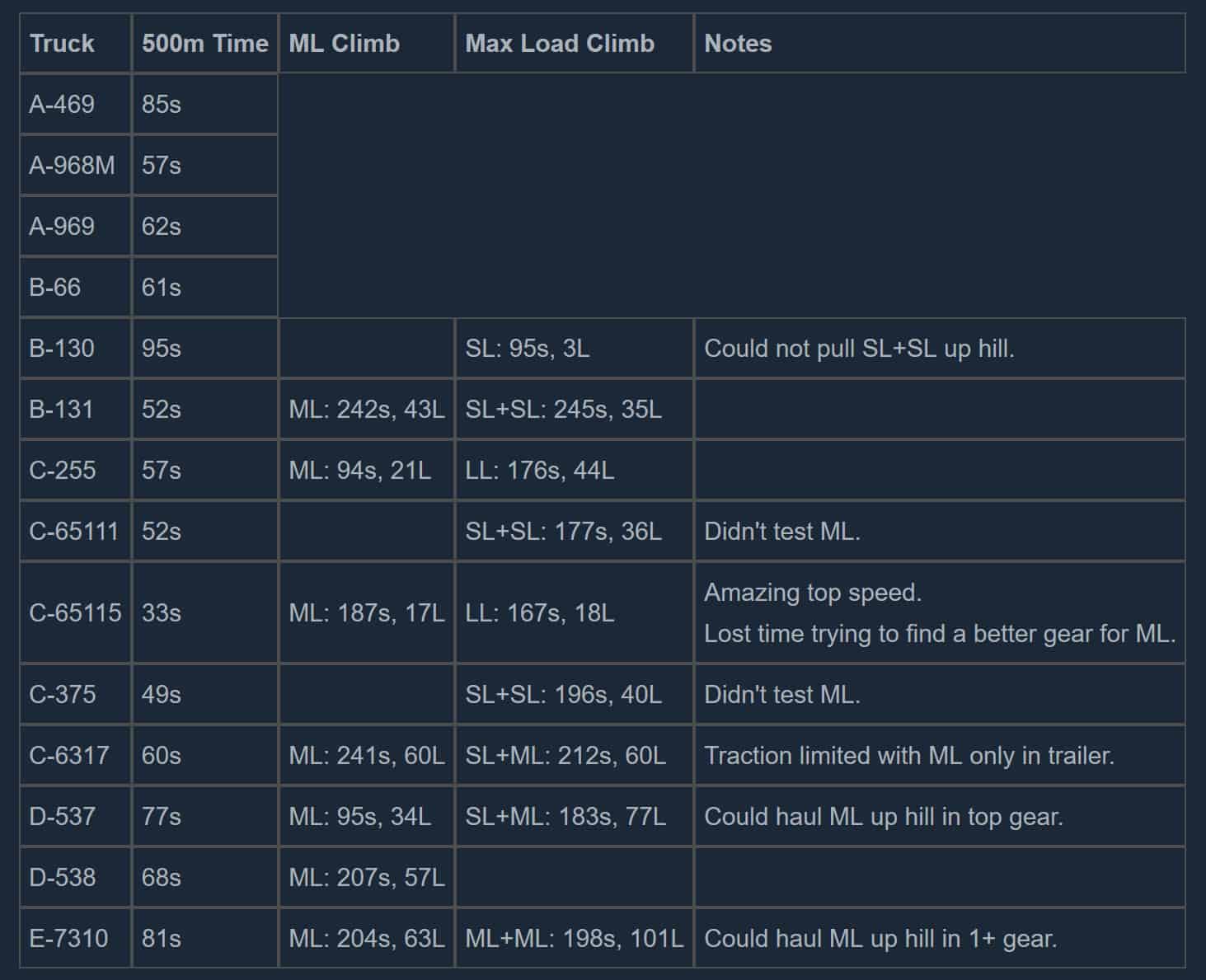
American Trucks
I do not have reference information for trucks from the American Wilds expansion because I do not have the expansion (yet). I can only list what the trucks turn into for people who don’t have the expansion:
- chevrolet_bison_1978 (requires American Wilds, else B-131)
- chevrolet_k5_blazer (requires American Wilds, else A-469)
- ford_f150 (requires American Wilds, else A-469)
- fort_ltl9000 (requires American Wilds, else B-131)
- freightliner_fl120 (requires American Wilds, else B-131)
- hummer_h1 (requires American Wilds, else A-469)
- k8400_skidder (requires American Wilds, else C-255)
- k9000_forwarder (requires American Wilds, else C-255)
- westernstar_6900xd (requires American Wilds, else C-255)
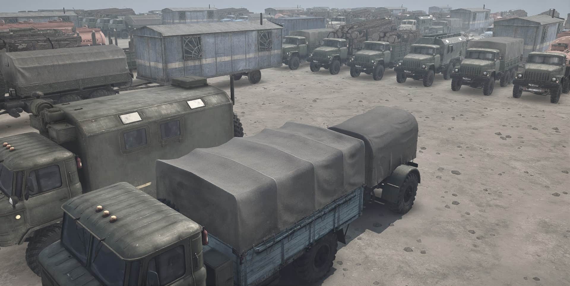
Truck Reference (A and B Classes)
Be sure to check the Truck Reference Introduction section above to best understand this reference.
A-Class Jeeps
A-469 = uaz469 (no logs) (RWD) (★ recallable)
A-3151 = uaz469_roof (no logs) (RWD) (★ recallable)
Cab addons:
- Spare Wheel = uaz_backup_wheel (60R)
- Trunk = uaz_trunk (80F, 200R)
A-Class Sedans
A-968M = zaz968m or zaz968m_blue (no logs) (RWD) (0 balance points; recallable)
Cab addons:
- Garage Parts = zaz_fridge (1G)
A-Class Van
A-969 = luaz969m (no logs) (FWD) (★ recallable) (requires The Valley, else A-469)
Cab addons:
- Spare Wheel = luaz_backup_wheel (60R)
Bed addons:
- Fuel Canisters = luaz_barrels (200F)
- Garage Parts = luaz_garage (1G)
- Utility Attachment = luaz_utility (60F, 200R)
B-6A
B-6A = umz6a (no logs) (RWD) (★ recallable) (requires The Ridge, else A-469)
Cab addons:
- Fuel Canisters = umz_canisters (120F)
Trailers:
- Fuel Trailer = umz_trailer_cisterm (900F)
- Utility Trailer = umz_trailer_utility (300F, 400R) (starts with full capacity of repair points)
B-66
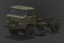
B-66 = gaz66 (no logs) (★★)
Cab addons:
- Spare Wheel = gaz_backup_wheel (80R) (conflicts with full-length addons)
Bed addons:
- Garage Utility Tent = gaz_zil_utility (400F, 200R, 1G)
Full-length addons:
- Utility Attachment = gaz_utility (600R, 1G)
Trailers:
- Garage Cart = trailer_gaz (1G)
B-130
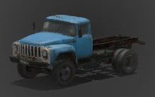
B-130 = zil130 (SL+SL, no crane) (RWD) (★)
Bed addons:
- Garage Utility Tent = zil_utility (400F, 200R, 1G)
- Log Carriage = zil_carriage – carries load_logs_short_short (SL, but only 2 load points!)
- Trailer Hitch = kraz_tractor
Trailers:
- Fuel Trailer = trailer_cistern_cart (1600F)
- Garage Cart = trailer_gaz (1G)
- Garage Trailer = trailer_vagon (2G)
- Utility Trailer = trailer_utility_cart (600F, 600R)
- Short Log Trailer = trailer_short_cart – carries load_logs_short_trailer (SL, says 2 load points when trailer is attached, but picks up and delivers 3 load points)
Semi-trailers (all require trailer hitch):
- Fuel Semi-Trailer = trailer_cistern (3700F)
- Garage Semi-Trailer = trailer_tent (4G)
- Utility Semi-Trailer = trailer_utility (900F, 1200R)
B-131
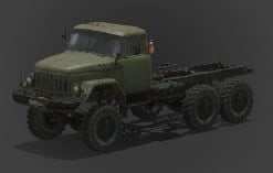
B-131 = zil131 (SL+SL or ML, no crane) (★★)
Cab addons:
- Fireproof Exhaust = ural_exhaust
- Spare Wheel = zil_backup_wheel (100R) (conflicts with full-length addons)
Bed addons:
- Fuel Cistern = zil_cistern (900F) (requires fireproof exhaust)
- Trailer Hitch = kraz_tractor
Full-length addons:
- Garage Parts = kraz_tent (2G)
- Utility Attachment = zil_kraz_utility (600R, 1G)
- Log Carriage = kraz_carriage – carries load_logs_short (SL)
- Log Carrier = kraz_cart
Trailers:
- Fuel Trailer = trailer_cistern_cart (1600F)
- Garage Cart = trailer_gaz (1G)
- Garage Trailer = trailer_vagon (2G)
- Utility Trailer = trailer_utility_cart (600F, 600R)
- Short Log Trailer = trailer_short_cart – carries load_logs_short_trailer (SL)
- Medium Log Cart = trailer_cart (requires log carrier) – carries load_logs_medium (ML)
Semi-trailers (all require trailer hitch):
- Fuel Semi-Trailer = trailer_cistern (3700F) (requires fireproof exhaust)
- Garage Semi-Trailer = trailer_tent (4G)
- Utility Semi-Trailer = trailer_utility (900F, 1200R)
Truck Reference (C Class)
Be sure to check the Truck Reference Introduction section above to best understand this reference.
C-2xx, C-4310, and C-6511x
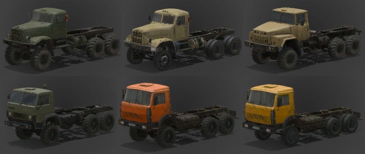
C-255 = kraz255 (SL+SL with crane; SL+SL, ML, or LL without crane) (★★★)
C-256 = kraz256 (SL+SL with crane; SL+SL, ML, or LL without crane) (★ !)
C-260 = kraz260 (SL+SL or ML with crane; SL+SL, ML, or LL without crane) (★★★)
C-4310 = kamaz4310 (ML with crane; SL+SL or ML without crane) (★★★)
C-65111 = kamaz65111 (SL+SL or ML with or without crane) (★★★)
C-65115 = kamaz65115 (SL+SL, ML, or LL, no crane) (RWD) (0 balance points!)
Cab addons:
- Crane Support = ural_crane_support (C-260 and C-4310 only)
- Fireproof Exhaust = ural_exhaust (C-4310 only)
- Spare Wheel = kraz_backup_wheel (C-255), kraz_backup_double (C-256), kraz_backup_wheel_new (C-260), or kamaz_backup_wheel (C-4310 or C-6511x) (100R) (conflicts with full-length addons)
Bed addons:
- Garage Parts = kraz_tent (C-2xx) or kamaz_tent (C-4310 or C-6511x) (2G)
- Utility Attachment = kraz_utility (C-2xx) or kamaz_utility (C-4310 or C-6511x) (800R, 1G)
- Log Carriage = kraz_carriage (C-2xx) or kamaz_carriage (C-4310 or C-6511x) – carries load_logs_short (SL)
- Log Carrier = kraz_cart
- Log Carrier with Crane = ural_cart (C-260 and C-65111 only) (requires crane support for C-260)
- Trailer Hitch = kraz_tractor
Full-length addons:
- Fuel Cistern = kraz_cistern (1400F) (requires fireproof exhaust for C-4310)
- Log Crane Carriage = kraz_cart_crane (C-2xx and C-65111 only) – carries load_logs_short_crane (SL)
Trailers:
- Fuel Trailer = trailer_cistern_cart (1600F)
- Garage Trailer = trailer_vagon (2G)
- Utility Trailer = trailer_utility_cart (600F, 600R)
- Short Log Trailer = trailer_short_cart – carries load_logs_short_trailer (SL)
- Medium Log Cart = trailer_cart – carries load_logs_medium (ML) (requires log carrier or log carrier with crane)
- Long Log Cart = trailer_kraz_cart (C-2xx and C-65115 only) – carries load_logs_long (LL) (requires log carrier [without crane])
Semi-trailers (all require trailer hitch):
- Fuel Semi-Trailer = trailer_cistern (3700F) (requires fireproof exhaust for C-4310)
- Garage Semi-Trailer = trailer_tent (4G)
- Utility Semi-Trailer = trailer_utility (900F, 1200R)
C-375 and C-4320*
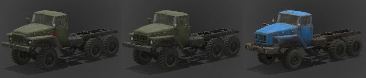
C-375 = ural375 (SL+SL with crane; SL+SL or ML without crane) (★★★)
C-4320 = ural4320 (SL+SL with crane; SL+SL or ML without crane) (0 balance points!)
C-432010 = ural4320_long (SL+SL with crane; SL+SL or ML without crane) (★★★)
The C-432010 uses different parts with different lengths for garage parts and log carriage.
Cab addons:
- Crane Support = ural_crane_support
- Fireproof Exhaust = ural_exhaust
- Spare Wheel = ural_backup_wheel (100R) (conflicts with full-length addons)
Bed addons:
- Fuel Cistern = ural_cistern (1200F) (requires fireproof exhaust)
- Garage Parts = kraz_tent (2G) (C-375 and C-4320 only)
- Log Carriage = kraz_carriage (C-375 and C-4320 only) – carries load_logs_short (SL)
- Log Carrier = kraz_cart
- Trailer Hitch = kraz_tractor
Full-length addons:
- Garage Parts = kamaz_tent (2G) (C-432010 only)
- Utility Attachment = kraz_utility (800R, 1G)
- Log Carriage = kamaz_carriage (C-432010 only) – carries load_logs_short (SL)
- Log Carrier with Crane = ural_cart (requires crane support)
Trailers:
- Fuel Trailer = trailer_cistern_cart (1600F)
- Garage Trailer = trailer_vagon (2G)
- Utility Trailer = trailer_utility_cart (600F, 600R)
- Short Log Trailer = trailer_short_cart – carries load_logs_short_trailer (SL)
- Medium Log Cart = trailer_cart – carries load_logs_medium (ML) (requires log carrier or log carrier with crane)
Semi-trailers (all require trailer hitch):
- Fuel Semi-Trailer = trailer_cistern (3700F) (requires fireproof exhaust)
- Garage Semi-Trailer = trailer_tent (4G)
- Utility Semi-Trailer = trailer_utility (900F, 1200R)
C-6317
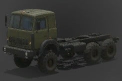
C-6317 = maz6317 (SL+SL or SL+ML with or without crane) (★★★) (requires The Valley, else C-255)
Cab addons:
- Spare Wheel = chip_backup_wheel (120R)
Bed addons:
- Fuel Cistern = kraz_cistern (1400F)
- Garage Parts = kamaz_tent (2G)
- Log Carriage = kamaz_carriage – carries load_logs_short (SL)
- Log Crane Carriage = kraz_cart_crane – carries load_logs_short_crane (SL)
- Trailer Hitch = kraz_tractor
Trailers:
- Fuel Trailer = trailer_cistern_cart (1600F)
- Garage Trailer = trailer_vagon (2G)
- Utility Trailer = trailer_utility_cart (600F, 600R)
- Short Log Trailer = trailer_short_cart – carries load_logs_short_trailer (SL)
- Medium Log Trailer = trailer_medium_cart – carries load_logs_medium_trailer (ML)
Semi-trailers (all require trailer hitch):
- Fuel Semi-Trailer = trailer_cistern (3700F)
- Garage Semi-Trailer = trailer_tent (4G)
- Utility Semi-Trailer = trailer_utility (900F, 1200R)
Truck Reference (D, E, and K Classes)
Be sure to check the Truck Reference Intro section above to best understand this reference.
D-535 and D-537
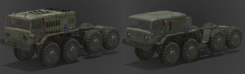
D-535 = maz535 (SL+SL or SL+ML, no crane) (0 balance points!)
D-537 = maz537 (SL+SL or SL+ML, no crane) (★★★★)
Cab addons:
- Spare Wheel = ural_backup_wheel (100R) (D-537 only) (conflicts with full-length addons)
Bed addons:
- Garage Parts = kraz_tent (D-535) or kamaz_tent (D-537) (2G)
- Log Carriage = kraz_carriage (D-535) or kamaz_carriage (D-537) – carries load_logs_short (SL)
Full-length addons:
- Trailer Hitch = maz_tractor (100R)
Trailers:
- Fuel Trailer = trailer_cistern_cart (1600F)
- Garage Trailer = trailer_vagon (2G)
- Utility Trailer = trailer_utility_cart (600F, 600R)
- Short Log Trailer = trailer_short_cart – carries load_logs_short_trailer (SL)
- Medium Log Trailer = trailer_medium_cart – carries load_logs_medium_trailer (ML)
Semi-trailers:
- Garage Semi-Trailer = trailer_maz_platform (200F, 4G) (requires trailer hitch)
D-538
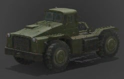
D-538 = maz538 (SL or ML with or without crane) (★★★★) (requires The Ridge, else C-255)
Bed addons:
- Fuel Canisters = maz538_barrels (700F)
- Spare Wheel = maz538_backup_wheel (120R)
- Loader = maz538_crane
Trailers:
- Fuel Trailer = trailer_cistern_cart (1600F)
- Garage Trailer = trailer_vagon (2G)
- Utility Trailer = trailer_utility_cart (600F, 600R)
- Short Log Trailer = trailer_short_cart – carries load_logs_short_trailer (SL)
- Medium Log Trailer = trailer_medium_cart – carries load_logs_medium_trailer (ML)
E-7xxx
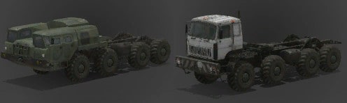
E-7310 = maz7310 (ML+SL or ML+ML, no crane) (★★★★★)
E-7429 = mzkt7429 (ML+SL or ML+ML, no crane) (★★★★★) (requires The Valley, else C-255)
These are the only Russian trucks that can carry 8 load points at once.
Cab addons:
- Repair Kit = mzkt_winch (100R) (E-7429 only) (conflicts with full-length addons)
Bed addons:
- Advanced Trailer Hitch = maz_big_tractor (100R) (E-7310 only)
- Trailer Hitch = mzkt_tractor (E-7429 only)
Full-length addons:
- Fuel Cistern = maz_big_cistern (2200F)
- Log Carrier = maz_big_cart – carries load_logs_medium_wide (ML)
Trailers:
- Fuel Trailer = trailer_cistern_cart (1600F)
- Garage Trailer = trailer_vagon (2G)
- Utility Trailer = trailer_utility_cart (600F, 600R)
- Short Log Trailer = trailer_short_cart – carries load_logs_short_trailer (SL)
- Medium Log Trailer = trailer_medium_cart – carries load_logs_medium_trailer (ML)
Semi-trailers:
- Garage Semi-Trailer = trailer_maz_platform (200F, 4G) (requires trailer hitch or advanced trailer hitch)
K-700
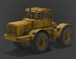
K-700 = kirovets700 (no logs with loader; SL or ML without loader) (★★★★)
Bed addons:
- Loader = kirovets_loader (conflicts with all trailers)
Trailers:
- Fuel Trailer = trailer_cistern_cart (1600F)
- Garage Trailer = trailer_vagon (2G)
- Utility Trailer = trailer_utility_cart (600F, 600R)
- Short Log Trailer = trailer_short_cart – carries load_logs_short_trailer (SL)
- Medium Log Trailer = trailer_medium_cart – carries load_logs_medium_trailer (ML)
Material Reference
The material selection window provides a simple view of each material, but more information is useful so that you don’t have to experiment. Therefore, this section provides that additional information for all materials.
Most materials are soft and can be rutted by truck tires. A few materials are hard and cannot be rutted by truck tires (except where mud has been manually created). Where a hard material blends with a soft material, the maximum depth of ruts is also smoothly blended for a natural transition.
Trucks can throw dust into the air when they drive straight on certain materials. (Trucks always throw dust when skidding.)
Some materials prevent certain plants from being placed on them using a distribution:
- Group A: ground leaves, strobiles, and debris chunks.
- Group B: birches, small trees (including small pines), bushes, mushrooms, herbs, ferns, flowers, daisies, grasses. Materials that exclude this group still allow a random jumble of plants such as large conifers, stumps, canes, pumpkins, etc.
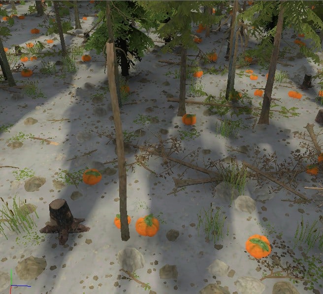
Finally, some materials come with their own 3-D grass or debris.
Materials Summary
beach:
- Soft. Generates dust.
- Excludes plants in group B above.
beach_dark:
- Soft. Generates dust.
- Excludes plants in group B above.
beach_dark_grass:
- Soft. Generates dust.
- Looks the same as beach_dark, but does not exclude plants.
concrete:
- Hard. Does not generate dust.
- Excludes plants in group B above.
dirt:
- Soft. Generates dust.
- Excludes plants in group B above.
- Includes sparse debris.
dirt_dark:
- Soft, but does not generate dust.
- Does not exclude plants.
- Includes sparse debris and dry grass.
forest:
- Soft, but does not generate dust.
- Excludes plants in group A above.
- Includes short grass.
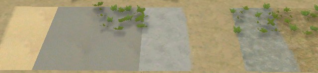
grass:
- Soft, but does not generate dust.
- Excludes plants in group A above.
- Includes tall grass.
moss:
- Soft, but does not generate dust.
- Excludes plants in group A above.
- Includes silvery grass.
rock_slope:
- Hard. Does not generate dust.
- Excludes plants in group B above.
rough:
- Soft, but does not generate dust.
- Excludes plants in group B above.
- Includes sparse debris.
soil:
- Soft, but does not generate dust.
- Does not exclude plants.
- Includes sparse debris and dry grass.
us_concrete:
- Hard. Does not generate dust.
- Excludes plants in group B above.
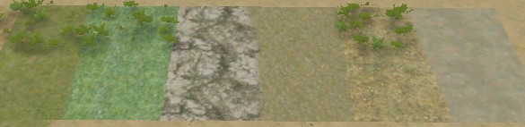
Distribution Reference
Each brush used by distributions is actually a combination of plants. This reference section helps you to anticipate what you’ll get.
Distribution brushes are grouped into natural categories for easier comparison. All images are taken from the same perspective within each category. This allows you to make an easy estimate of plant size and density.
Where plants are listed as singular, only one model is used. Where plural, multiple models are used.
Each plant is part of a “planting group” that limits its proximity to other plants in the same group, even if those other plants are part of a different distribution. The following abbreviations are used for planting groups. Some plants are part of multiple planting groups.
- BT = BigTree
- ST = SmallTree
- B = Bush
- LT = LyingTree
- D = Debris
- F = Flower
- G = Grass
When a brush uses multiple plant types, some may be limited to the upper or lower ends of the scale range. In other words, if you bias the scale randomness to one end of the scale or another, this implicitly biases the distribution of plant types used by the brush. Without going into excessive detail, the brush information below summarizes that bias.
- > – biased toward large scale
- < – biased toward small scale
Ground leaves, strobiles (cones), and debris chunks are blocked (not displayed) by the materials with dense grass: forest, grass, and moss. These are marked with BDGM.
Large Trees
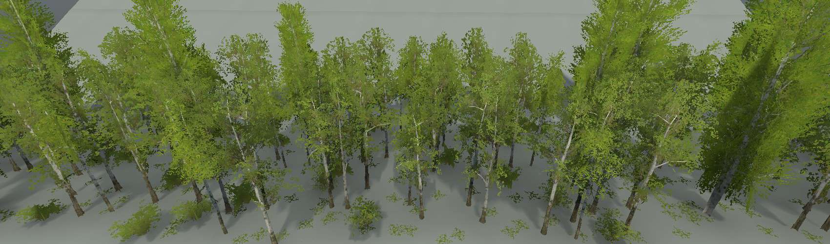
Birches
- big birch tree (BT, >)
- birch trees (BT, >)
- birch bush (BT, <)
- ground leaves (D, BDGM)
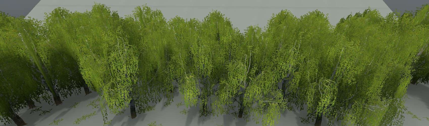
BirchesLong
- long birch tree (BT)
- ground leaves (D, BDGM)
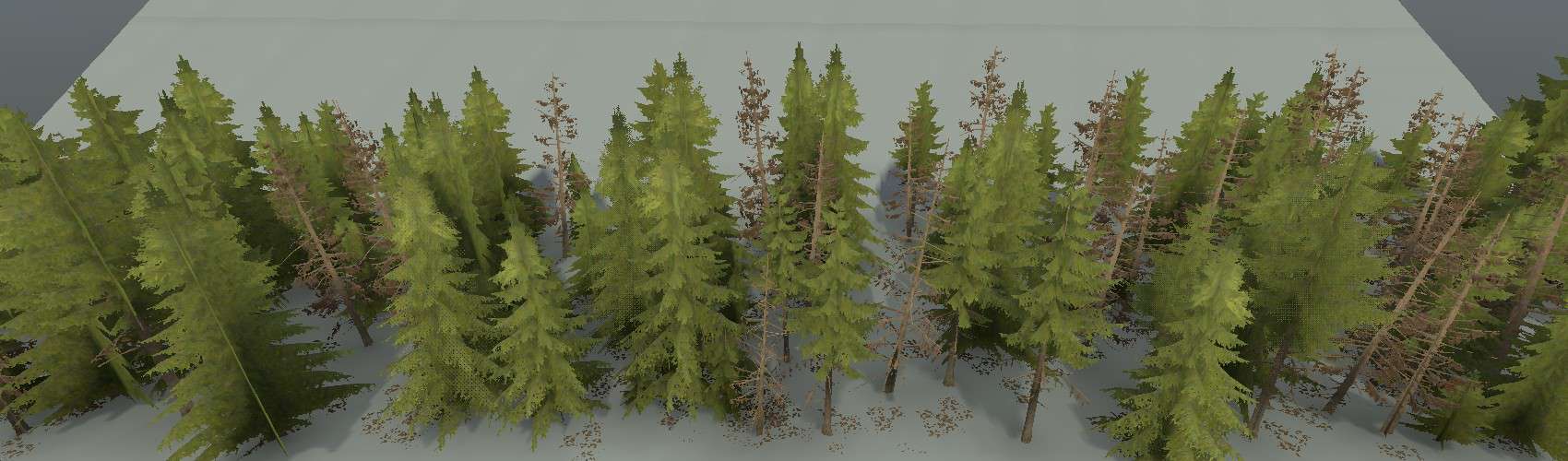
Firs
- firs (BT, >)
- dry fir (BT, >)
- small firs (B/ST, <)
- strobiles (D, BDGM)
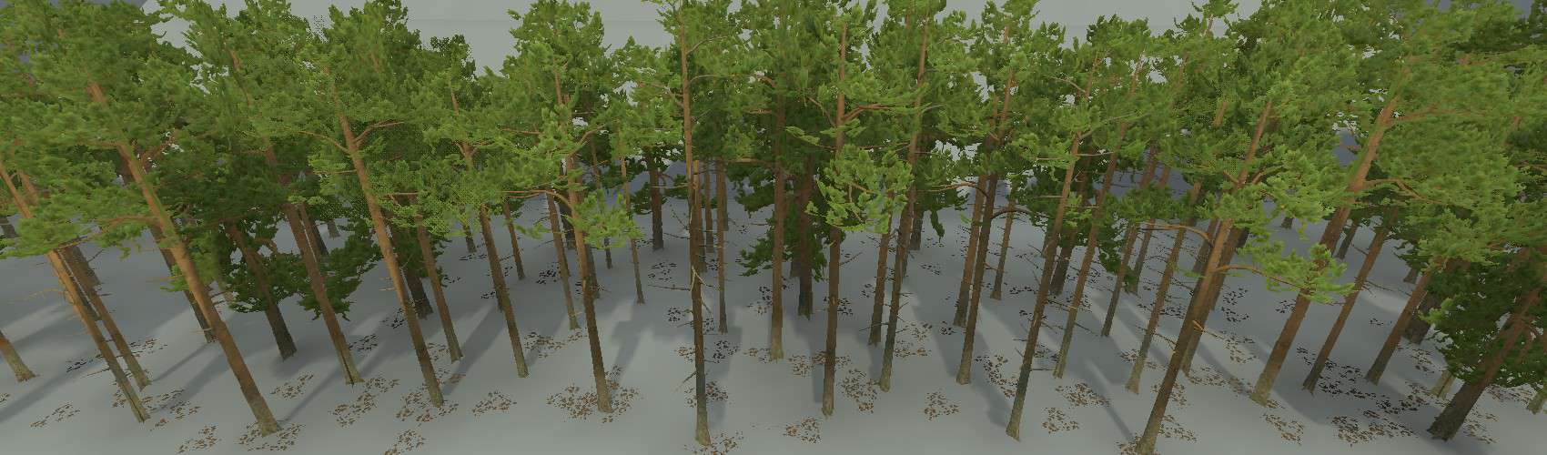
Pines
- pines (BT)
- strobiles (D, BDGM)
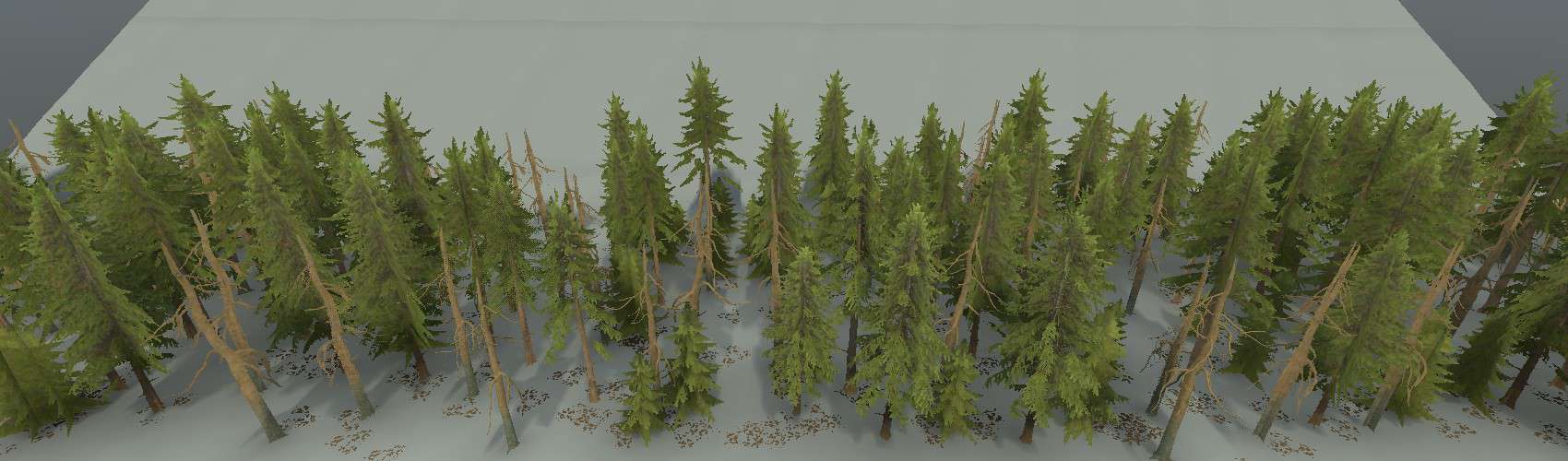
Spruces
- spruces (BT)
- dry pine (BT)
- small fir (B/ST, <)
- strobiles (D, BDGM)
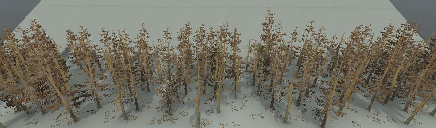
TreesDry
- dry fir (BT)
- dry pine (BT)
- strobiles (D, BDGM)
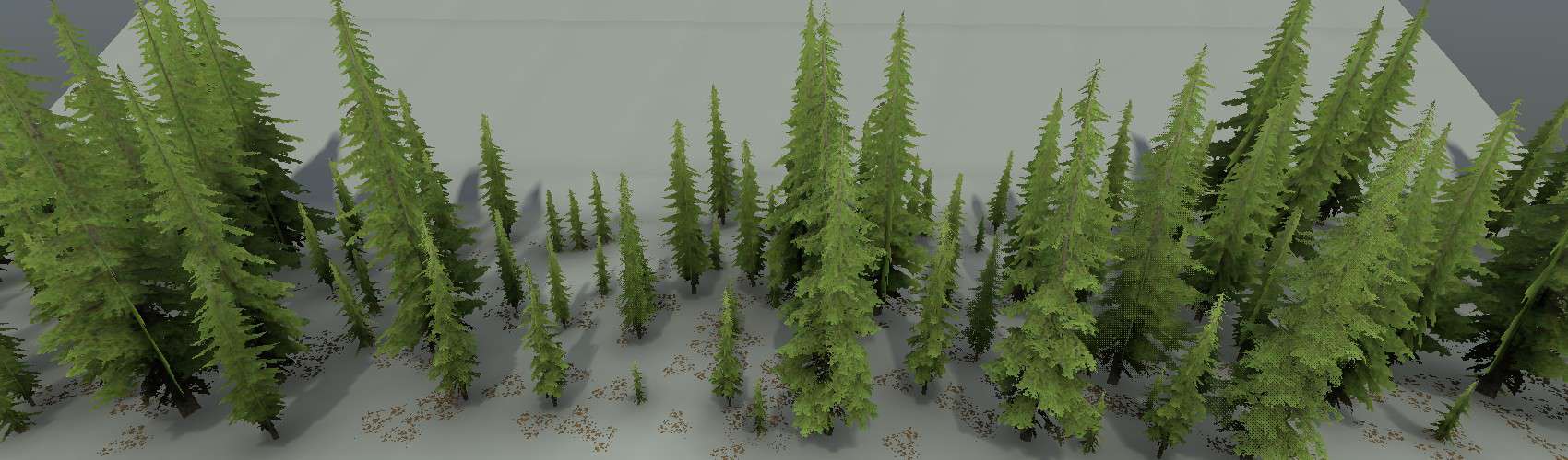
Tsugas
- US tsugas (BT)
- strobiles (D, BDGM)
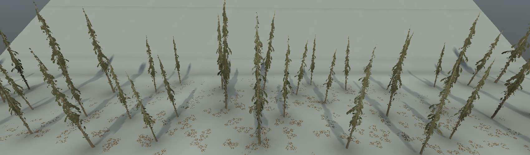
TsugasDry
- dry US tsugas (BT)
- strobiles (D, BDGM)
Bushes and Small Trees
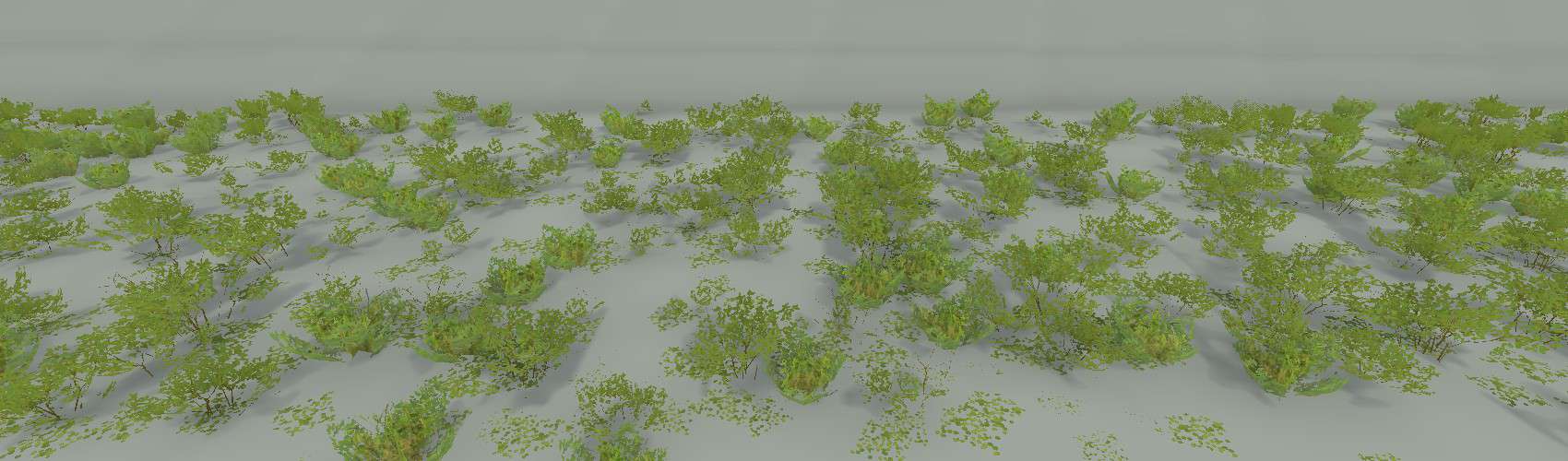
Bushes
- bushes (B/ST)
- ground leaves (D, BDGM)
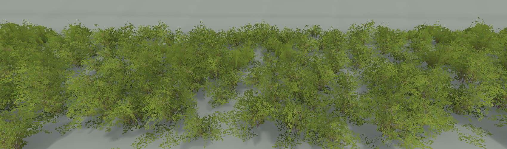
BushesBig
- birch bush (B/ST)
- ground leaves (D, BDGM)
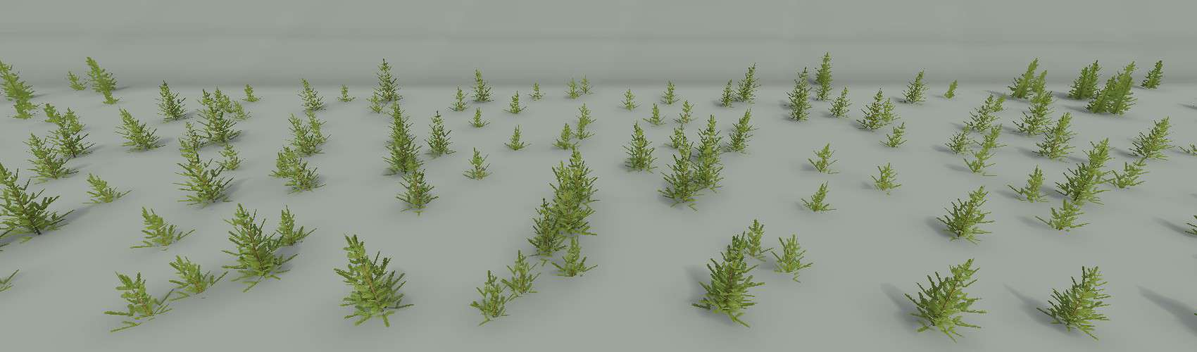
PinesSmall
- small pines (B/ST)
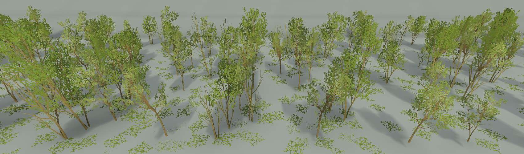
SmallTrees
- small trees (ST)
- small dry tree (ST)
- ground leaves (D, BDGM)
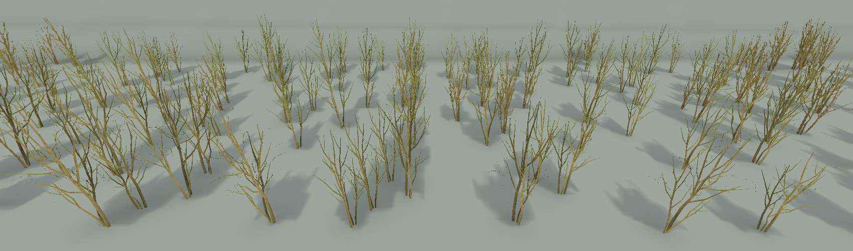
SmallTreesDry
- small dry tree (ST)
Tree Debris
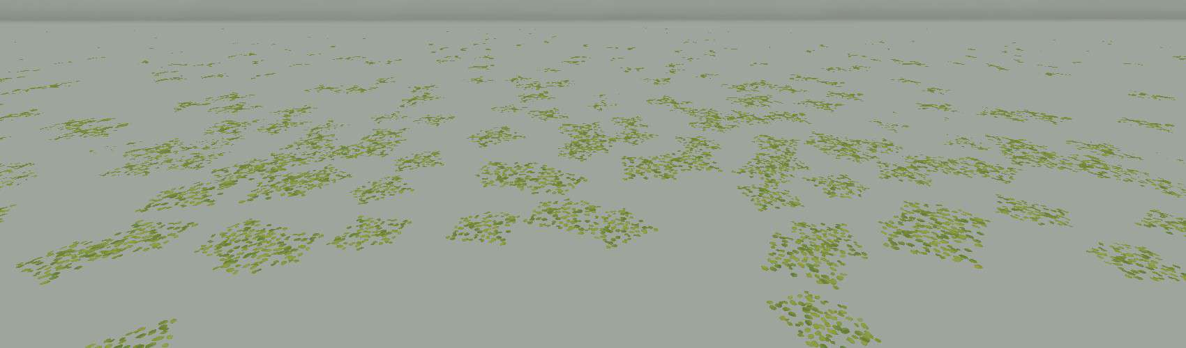
GroundLeaves
- ground leaves (D, BDGM)
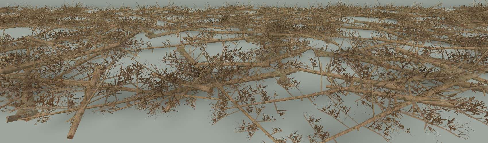
LyingFirs
- lying fir (LT, only placed where the ground is relatively flat)
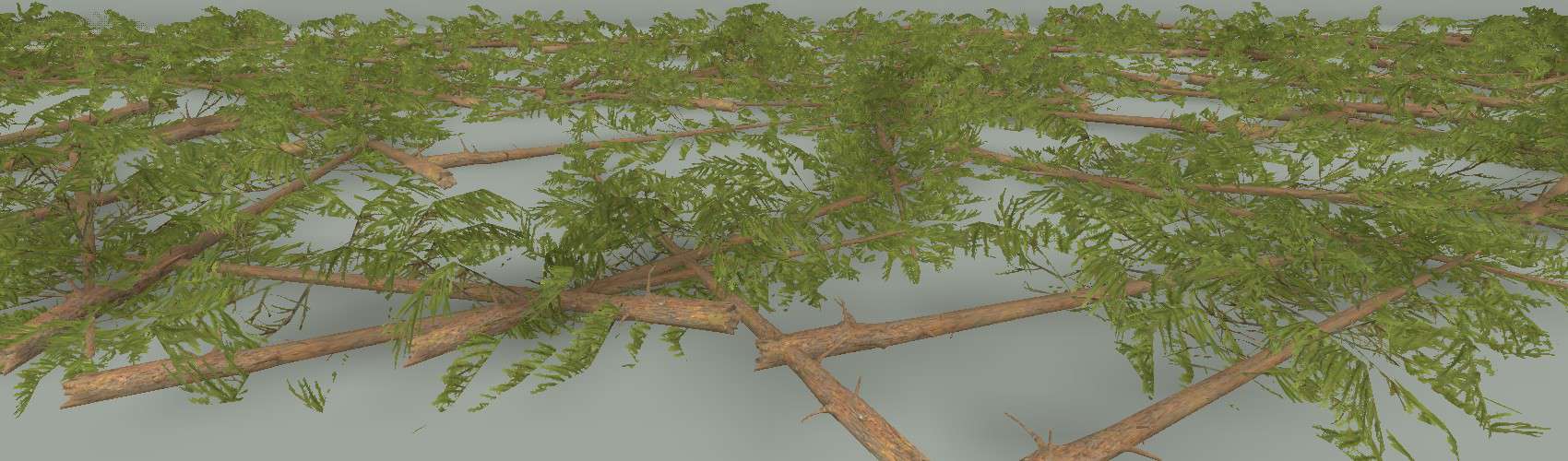
LyingSpruces
- lying spruce (LT, only placed where the ground is relatively flat)
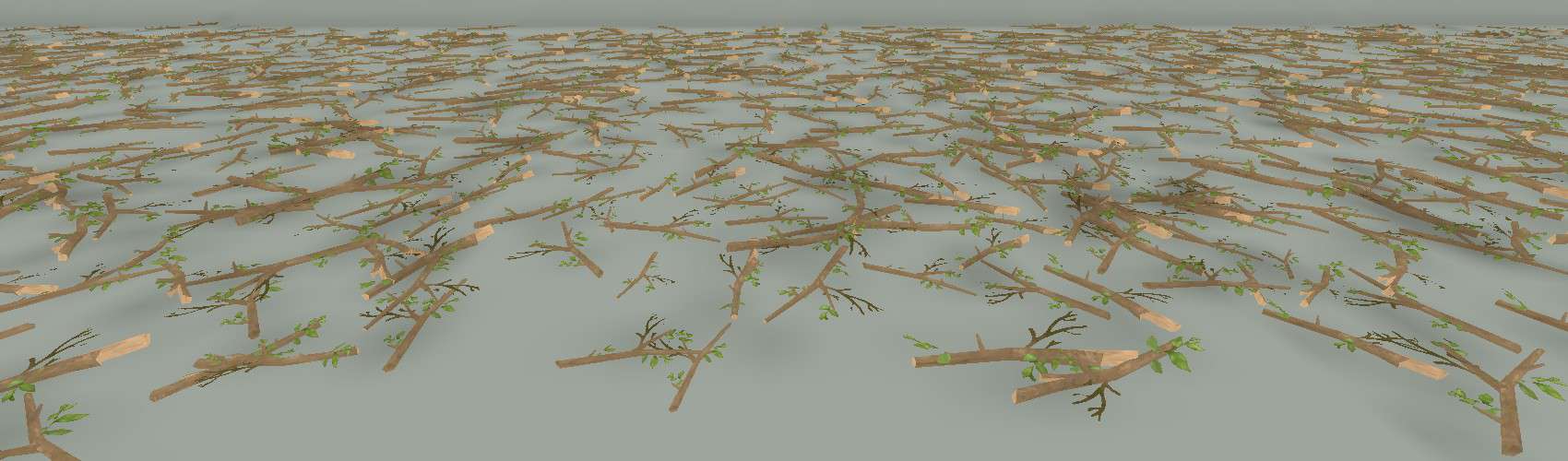
SmallTwigs
- small twigs (B/ST)
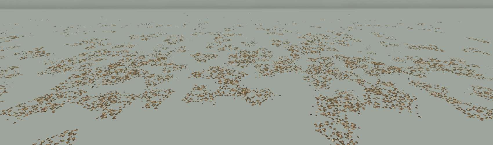
Strobiles
- strobiles (D, BDGM)
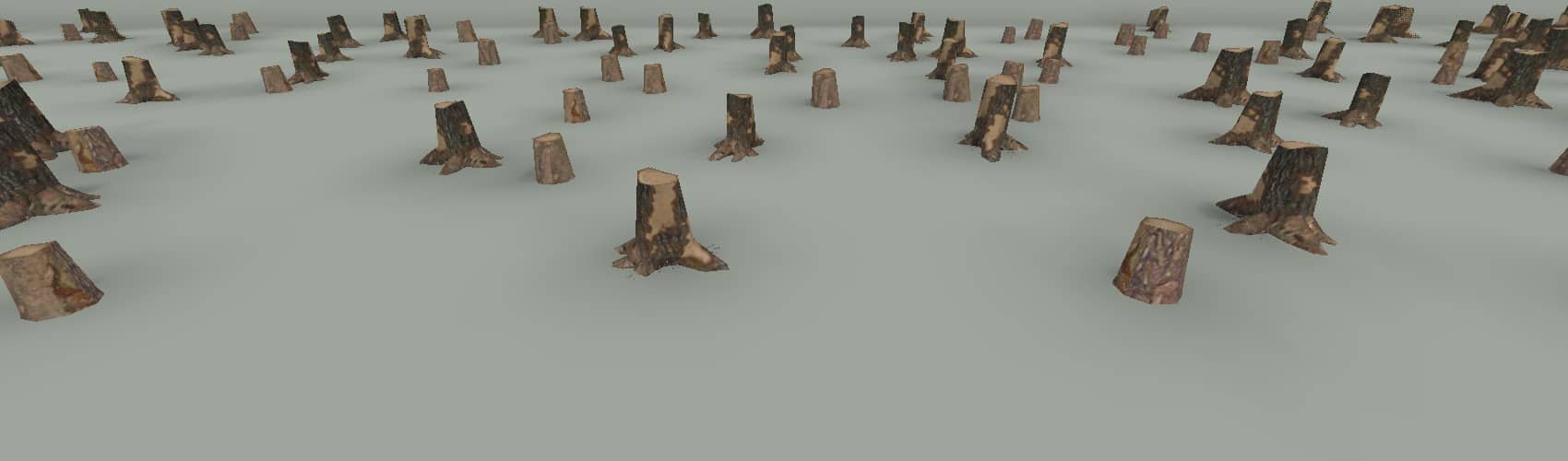
Stumps
- stumps (B/BT)
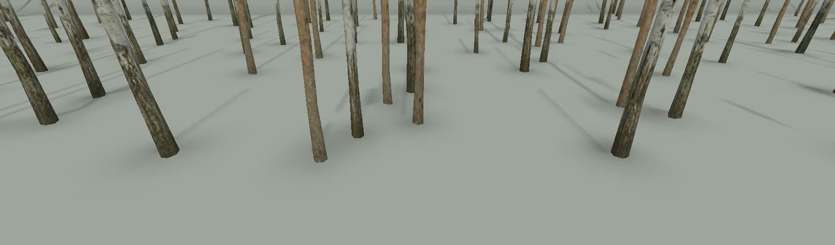
SwampStubsLong
- long swamp stubs (B/BT)
Small Plants
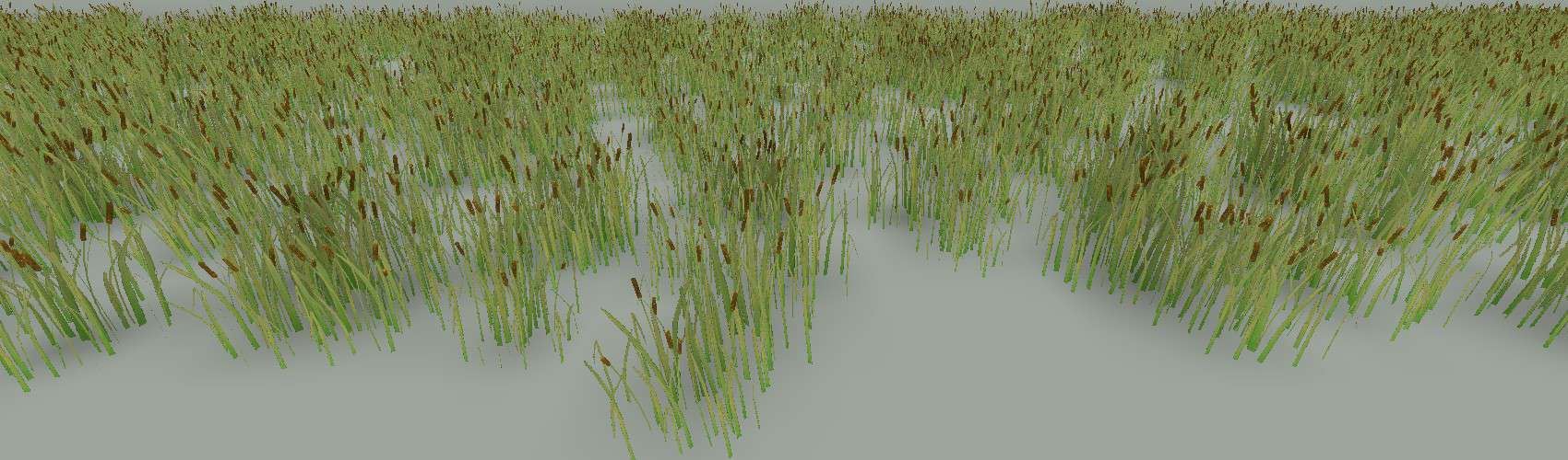
Canes
- cane with lily (in water) (F)
- cane without lily (on land) (F)
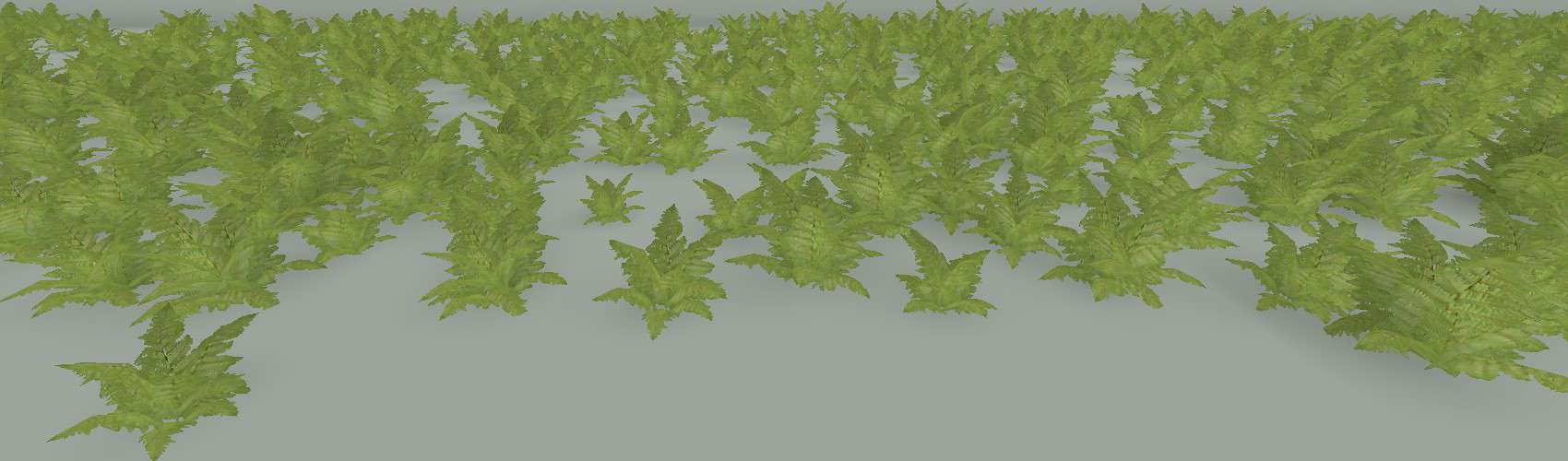
Ferns
- fern (B)
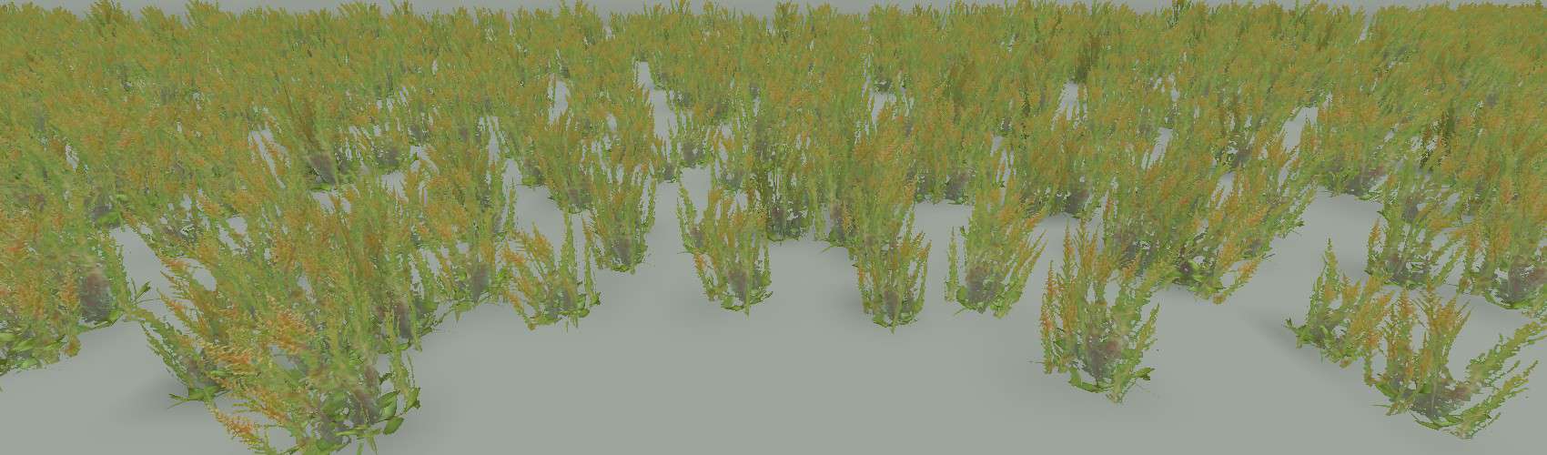
Herbs
- herb (F)
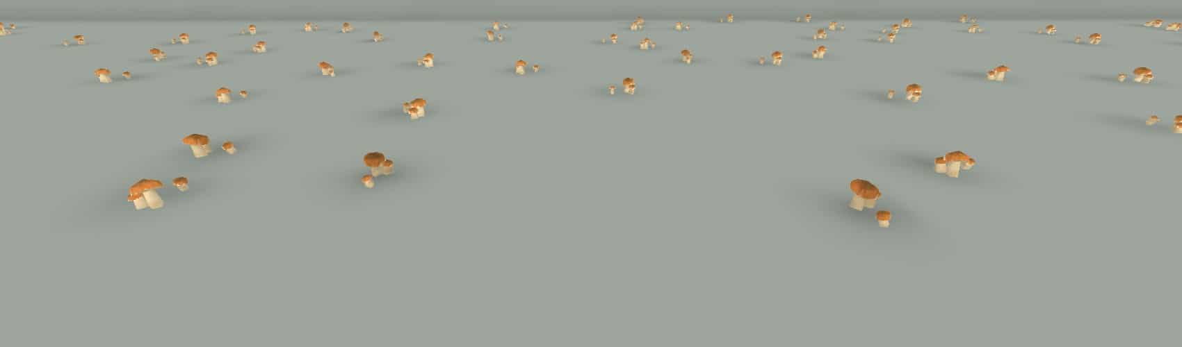
Mushrooms
- mushroom (F)
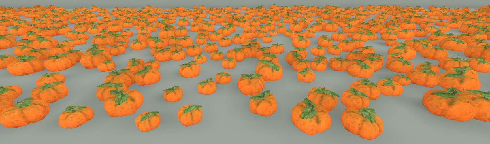
Pumpkins
- pumpkin (F)
Grasses and Flowers
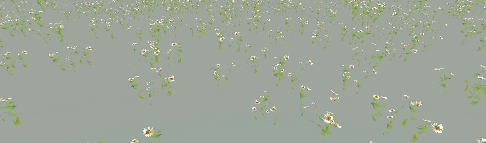
Daisy
- daisy (G)
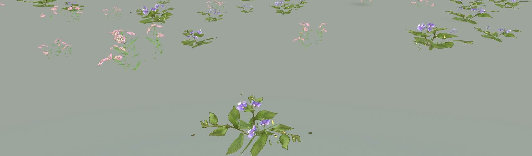
Flowers
- flowers (these glow at night) (F)
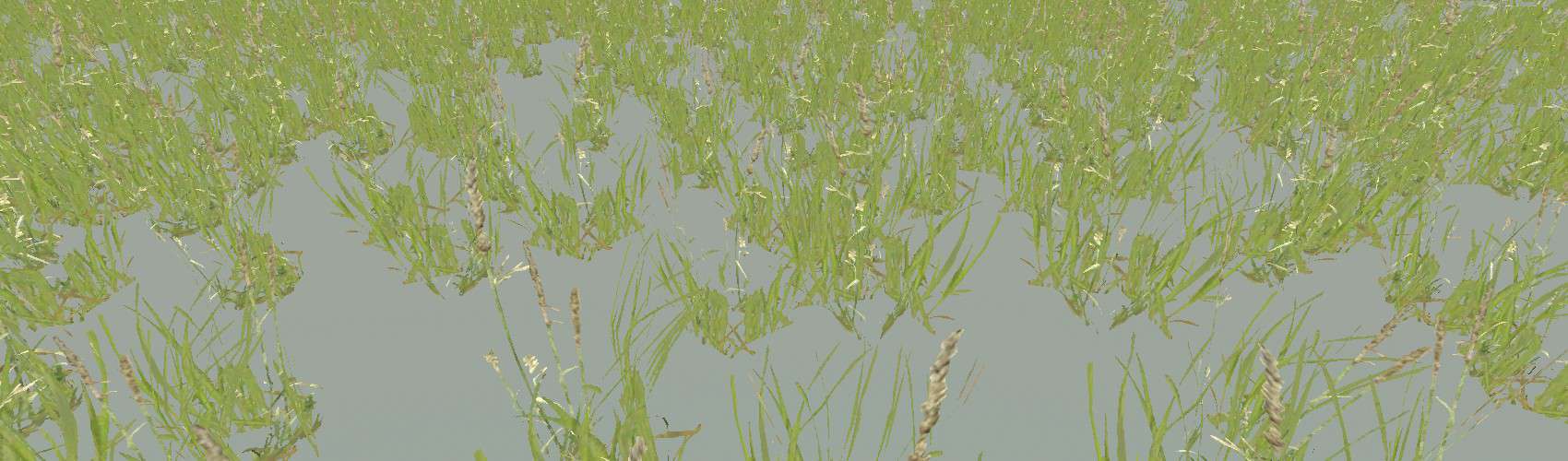
GrassLong
- wild grass with seeds (G)
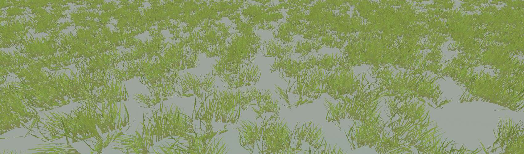
GrassMessy
- long green grass (G)
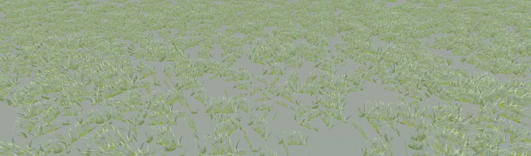
GrassMoss
- silvery grass (G)
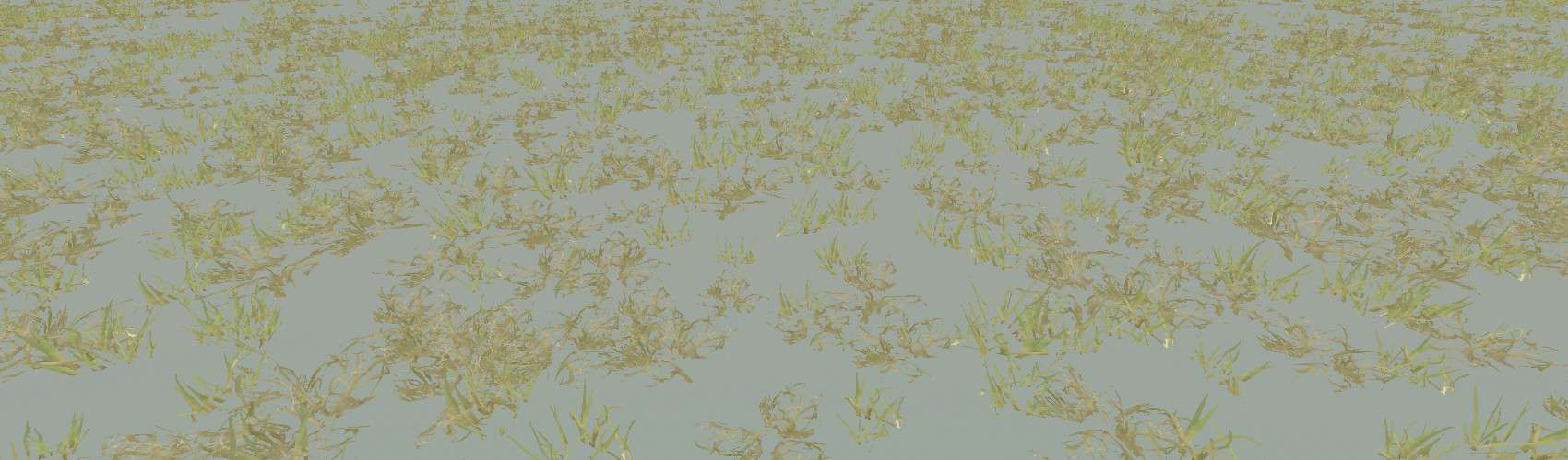
GrassShort
- short brownish green grass (G)
Rocks and Mud
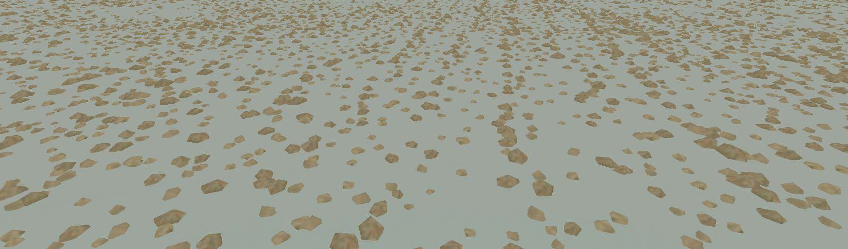
DebrisChunks
- debris chunks (B/ST)
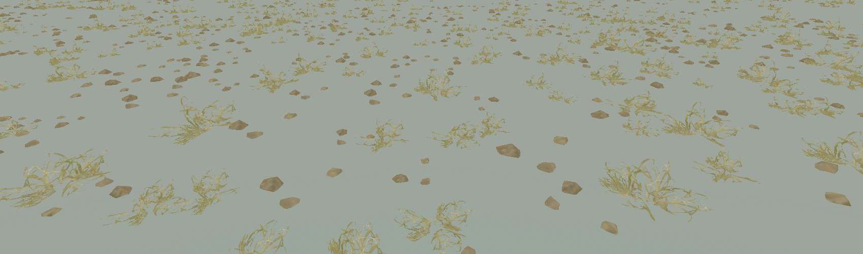
DebrisChunksSparse
- debris chunks (D, BDGM)
- dry grass (G)
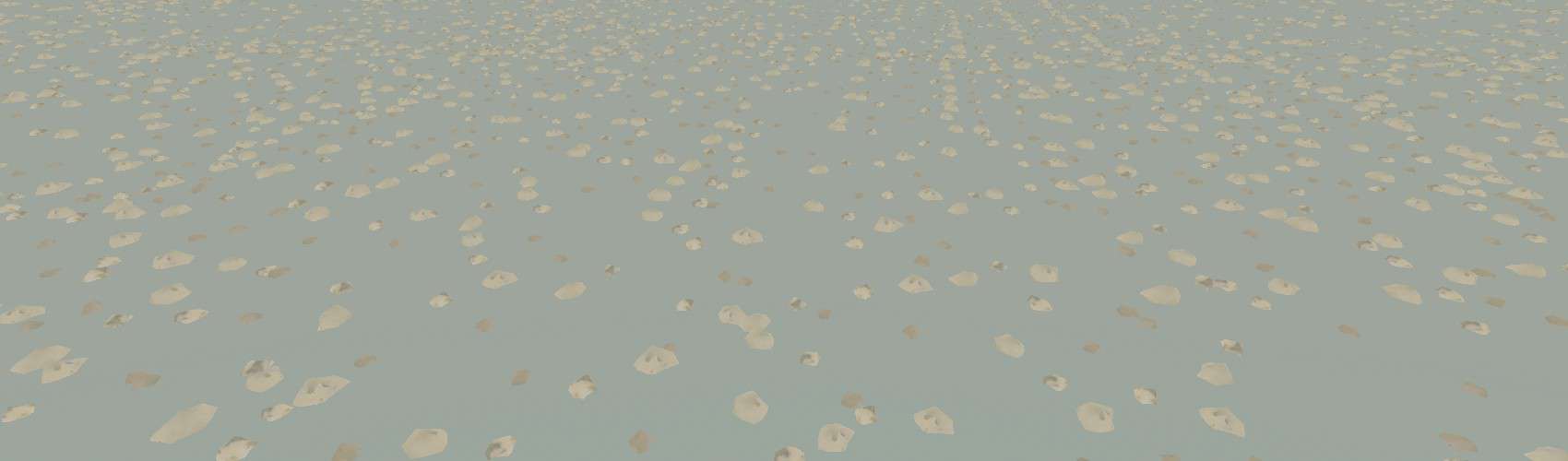
DebrisStones
- stone debris (D)
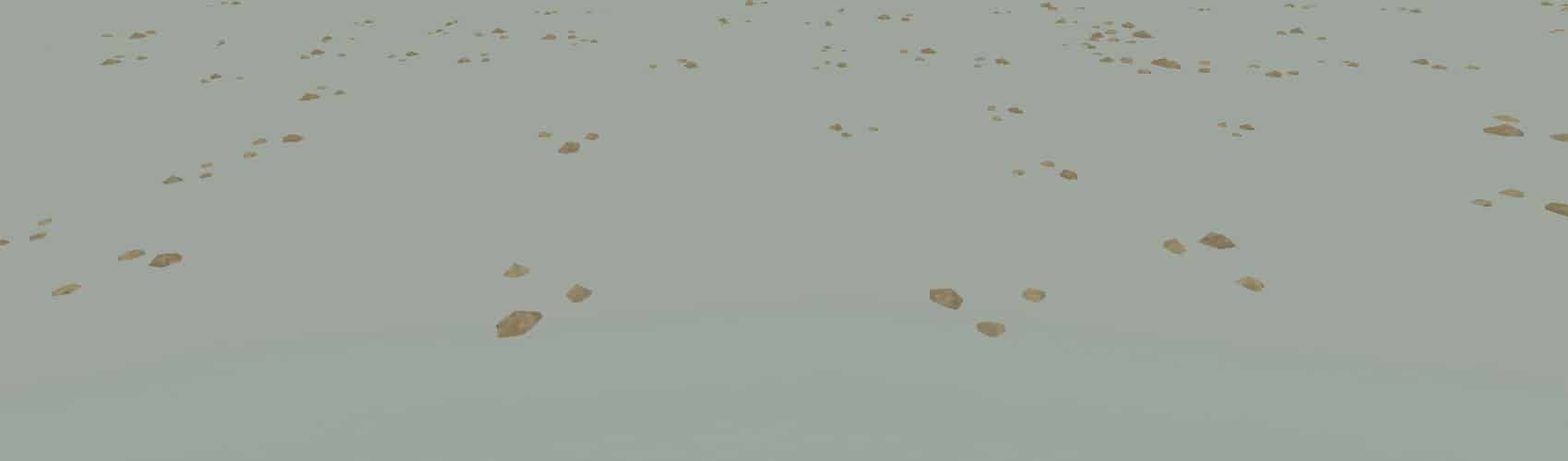
DebrisStonesSparse
- debris chunks (D, BDGM)
MudChunks
- mud chunks (B/ST)
- debris chunks (D, BDGM)
SmallRocks
- small rocks (B/ST)
- stone debris (D)
Road Reference
This section contains quick reference information for road overlays. Roads are listed in priority order, highest priority first. Roads listed together are all the same priority, in which case the first road listed in the Scene View gets priority in the tie break.
asphalt_road_double, usa_asphalt_road_double_2
- Hard (no ruts).
- Smooth.
- 8 meters wide (fixed)
- Excludes all plants.
- Drawn gray on navigation map.
asphalt_road
- Hard (no ruts).
- Smooth.
- 5 meters wide (fixed)
- Excludes all plants.
- Drawn gray on navigation map.
dirt_road, dirt_road_dark, dirt_road_smooth
- Soft (but it takes a lot of work to dig ruts).
- Slightly bumpy.
- 7 meters wide by default (adjustable).
- Excludes all plants.
- Drawn brown on navigation map.
grass_road
- Soft (but it takes a lot of work to dig ruts).
- Slightly bumpy and significant double-track ruts.
- 4 meters wide by default (adjustable).
- Excludes all plants.
- Drawn brown on navigation map.
dirt_path, dirt_wet_sand, dirt_wet_sand_dark
- Cannot be flattened.
- Soft (but it takes a lot of work to dig ruts).
- dirt_path is very bumpy. dirt_wet_sand and dirt_wet_sand_dark are smooth.
- 6 meters wide by default (adjustable).
- Excludes plants in group B as described in the Materials Reference section.
- Not drawn on navigation map.
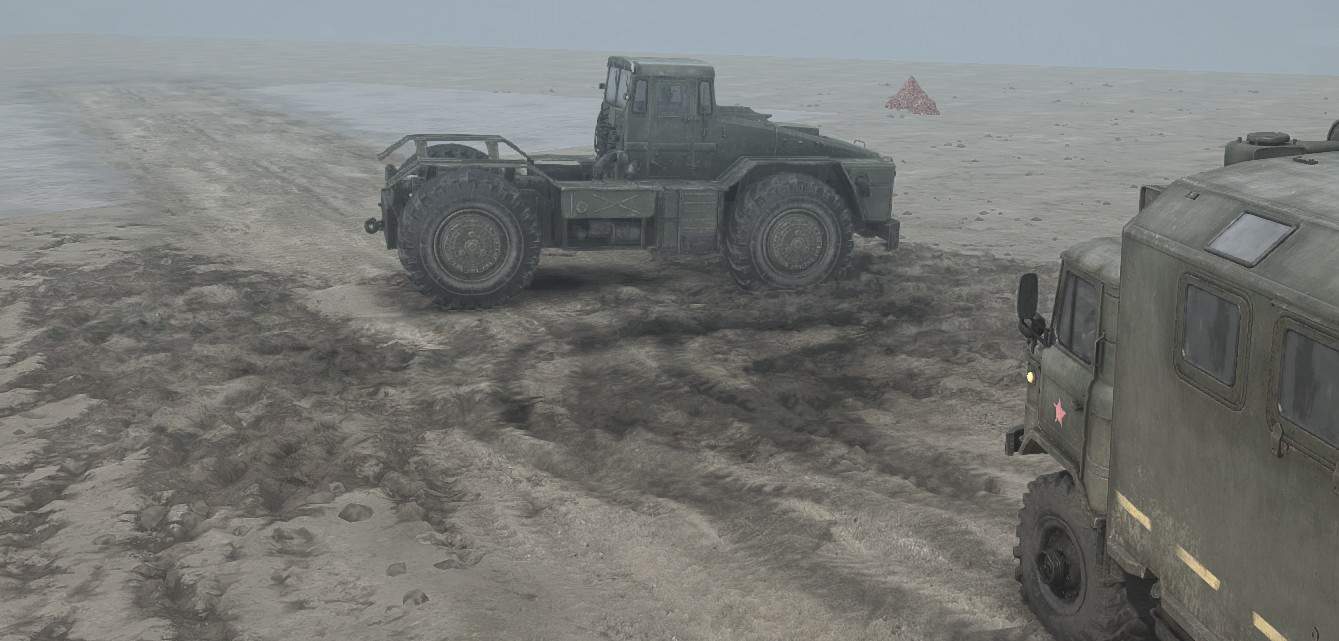
Model Reference (Signs)
Sign Reference
The signs are rotated oddly in the model selection window, so it’s hard to tell in advance what you’ll get. Here’s a reference.
Signs marked with a * have a graphic that doesn’t match the name. Use these with caution, as the developers may eventually change the model.
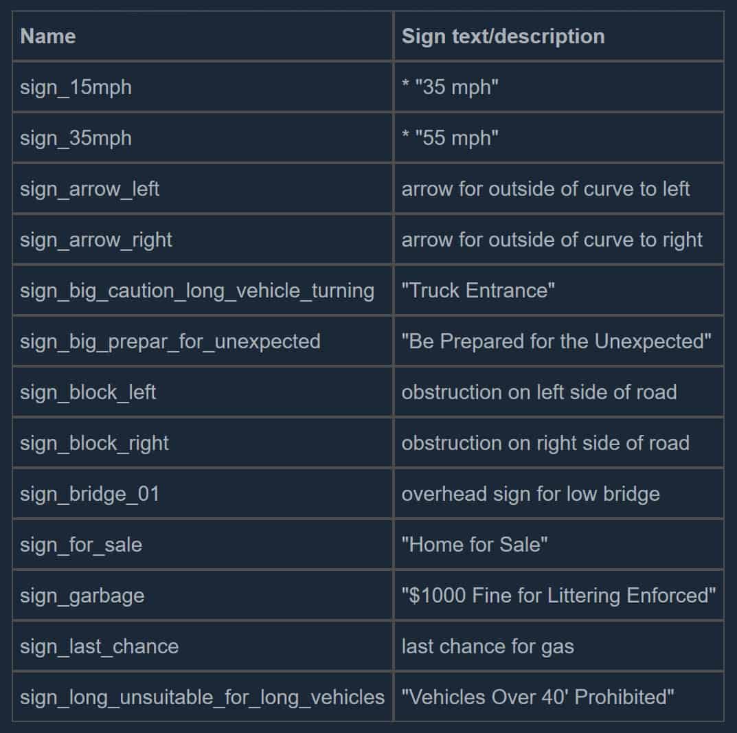
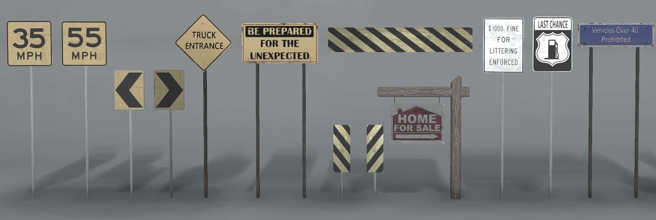
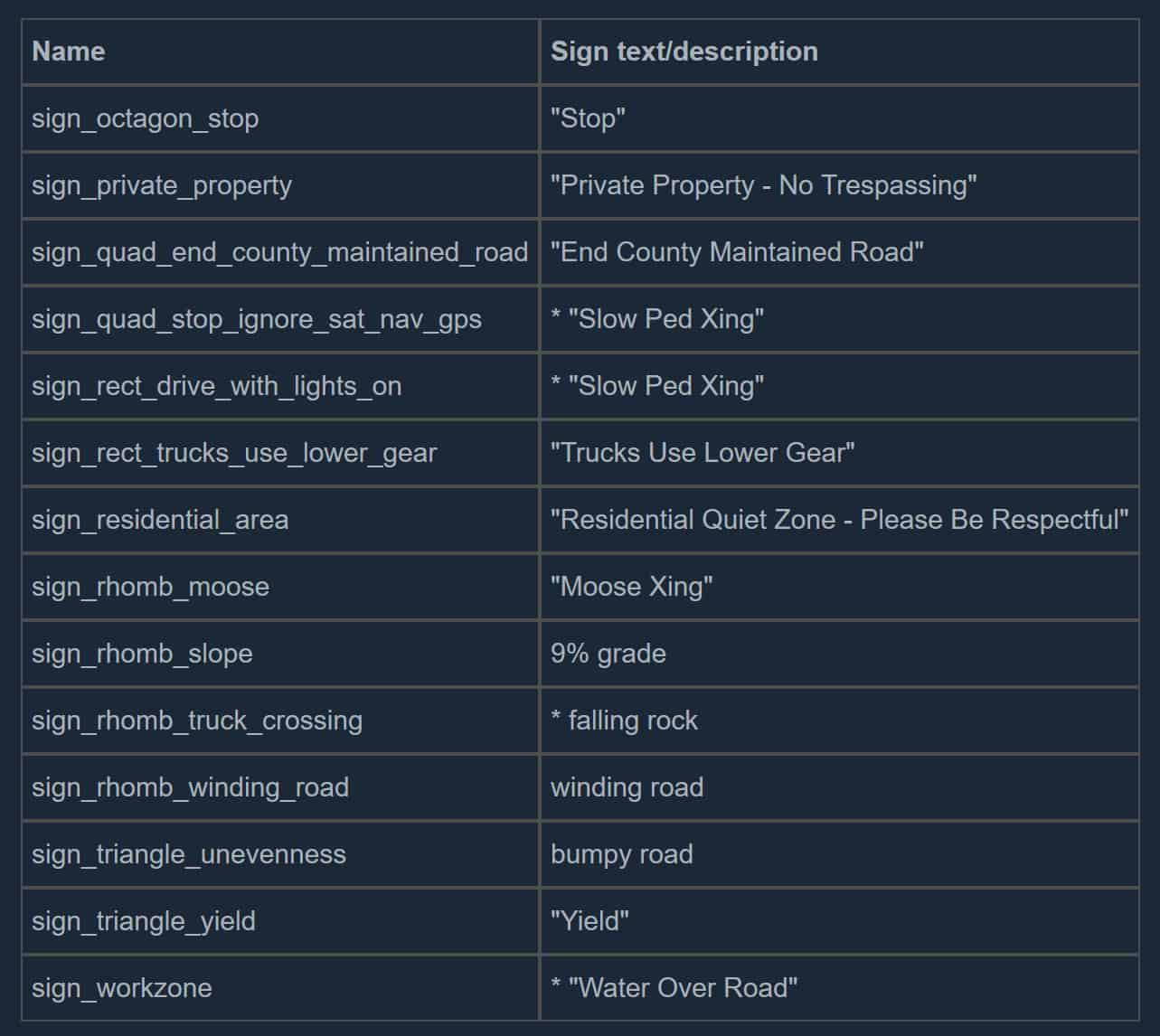
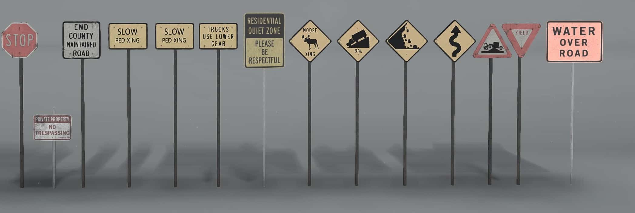
Mutator Reference
The following sections describe and show how the autumn and USA mutators differ from the original models. The mutator property is described in the Scene and Terrain Properties section.
Autumn
The deciduous trees (large and small) and bushes have fewer leaves, and their remaining leaves are yellow instead of green.
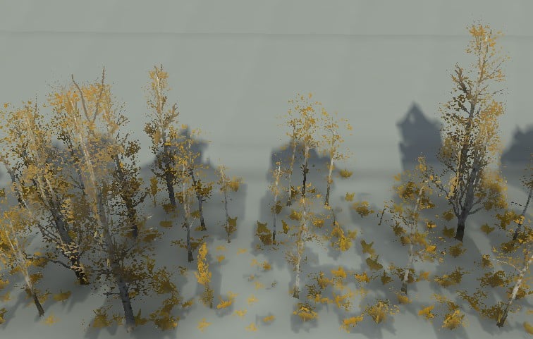
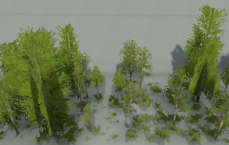
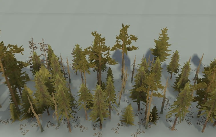
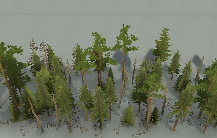
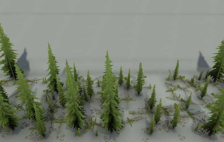
Canes, herbs, and ferns are a bit more yellow and are blotched with brown.
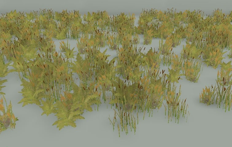
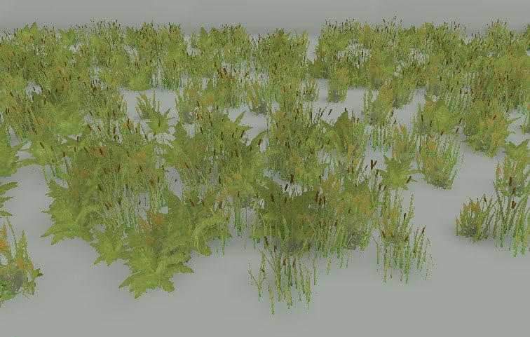
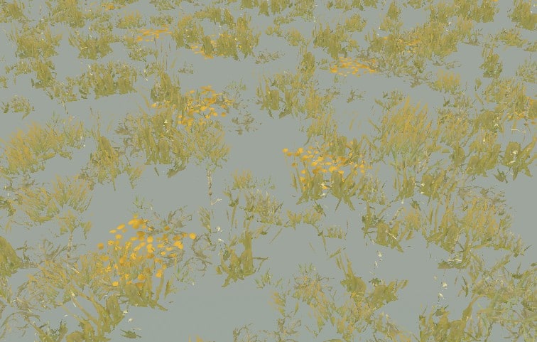
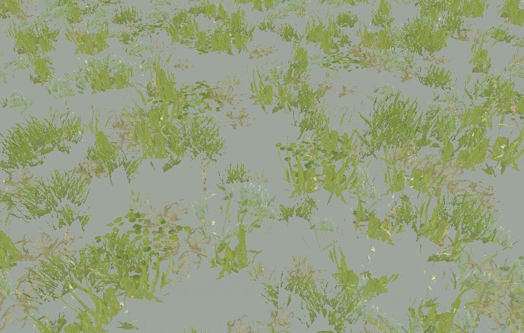
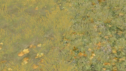
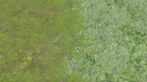
The dirt, beach, grass, rock slope, and soil materials have a strong reddish tinge. The dirt_wet_sand is supposed to also be tinged red, but the released files are named incorrectly, so it isn’t.
The cliff_dirt and cliff_soil overlays (not pictured) are tinged red to match the corresponding materials.
Mud is also tinged red, as are big rocks, stones, and mud chunks.
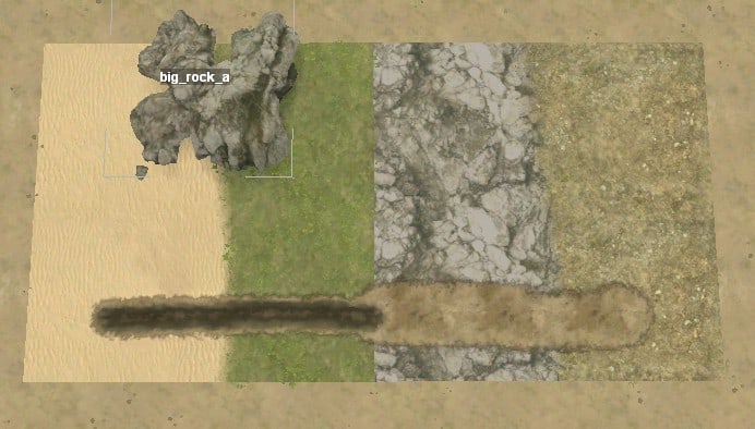
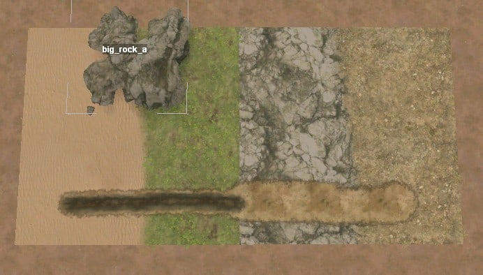
— Appendix B: Hand Edit the Map Files —
The MudRunner Editor makes it easy to edit your map and immediately see your changes. However, you sometimes need to do something that requires more power than what the editor offers or that is simply easier done outside the editor. The following sections describe what you need to know in order to edit files outside the MudRunner editor.
Hand Edit the Map’s XML
All information about your map is stored in the prebuild directory in either your map’s XML file or in your map’s bitmap directory. The XML file keeps a copy of all of the properties that the editor makes visible in the properties panel of the Scene View, and the bitmap directory store the images drawn with the various brush tools.
The XML file is just a text file, so it is easy to read and modify. Editing the XML by hand is useful for tasks that are difficult or impossible to do in the MudRunner Editor. For example, you can rearrange the trucks so that the active truck is first, followed by the starting trucks. Or you can globally change the Locked property to False for testing purposes.
Double clicking the XML file in the File View opens the map in the editor. To open only the XML file itself for editing, select the prebuild directory in the File View, then click the folder icon in the toolbar under the File View toolbar. This opens the directory in Windows Explorer. Double click the XML file in Windows Explorer to open the file in your XML editor.
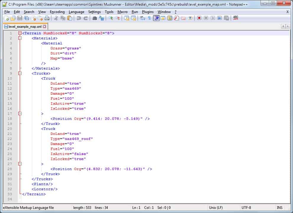
All properties are stored hierarchically inside named tags. For example, truck properties are under the < Trucks > tag, with one < Truck > tag for each individual truck. The properties for each truck should look familiar, although the exact names and formatting differ slightly from what is in the editor window.
The XML file is generally case sensitive, so you must use uppercase and lowercase exactly as you see it. A few property values are case insensitive. For example, the truck type can be “UAZ469” instead of “uaz469”. However, that may be MudRunner loads the truck from the uaz469.xml file, and the WIndows filesystem is case insensitive. The Linux filesystem is generally sensitive to case, so this file might fail on Linux. I recommend sticking with the default case as much as possible.
If you make any changes to the XML file while the MudRunner Editor is open, it will popup a dialog asking whether it should load the changes. Click “Yes” to do so.
The MudRunner Editor will generally perform reasonably if the XML is well formed but the values in it don’t make sense. It will make values self consistent where it can, and if some feature makes no sense at all, it simply won’t display it. Thus, you can freely experiment with different values without fear that everything will get screwed up. (That said, “undo” is your friend in the XML editor.)
You can sometimes edit the XML to exceed the limits imposed by the editor, but at your own risk. For example, I could change my map to 2048 x 2048, but the editor got so slow that I wouldn’t bother trying to create a real map that way. Beware also that something might work in the editor but not in the game itself.
Position Coordinate Systems
As mentioned in the “Navigate in the Main View” section, the X and Z axes define the ground plane, and the Y axis points up toward the sky. This section will describe the coordinate system in more detail.
Coordinates in Meters
Objects that can be detached from the ground is given coordinates in (X; Y; Z) format. An object that is always attached to the ground (such as a locator) uses the (X; Z) format. All object coordinates are measured in meters.
X and Z are measured from the center of the map:
- Positive X values are in the eastern half. Negative X values in the western half.
- Positive Z values in the northern half. Negative Z values are in the southern half.
Y coordinates on the land surface range from 0 at the lowest to 64 at the highest, although mud can deform the terrain slightly beyond these limits. The initial ground height is 20.078 meters, which is 80/255*64, roughly 1/3 of the maximum terrain height.
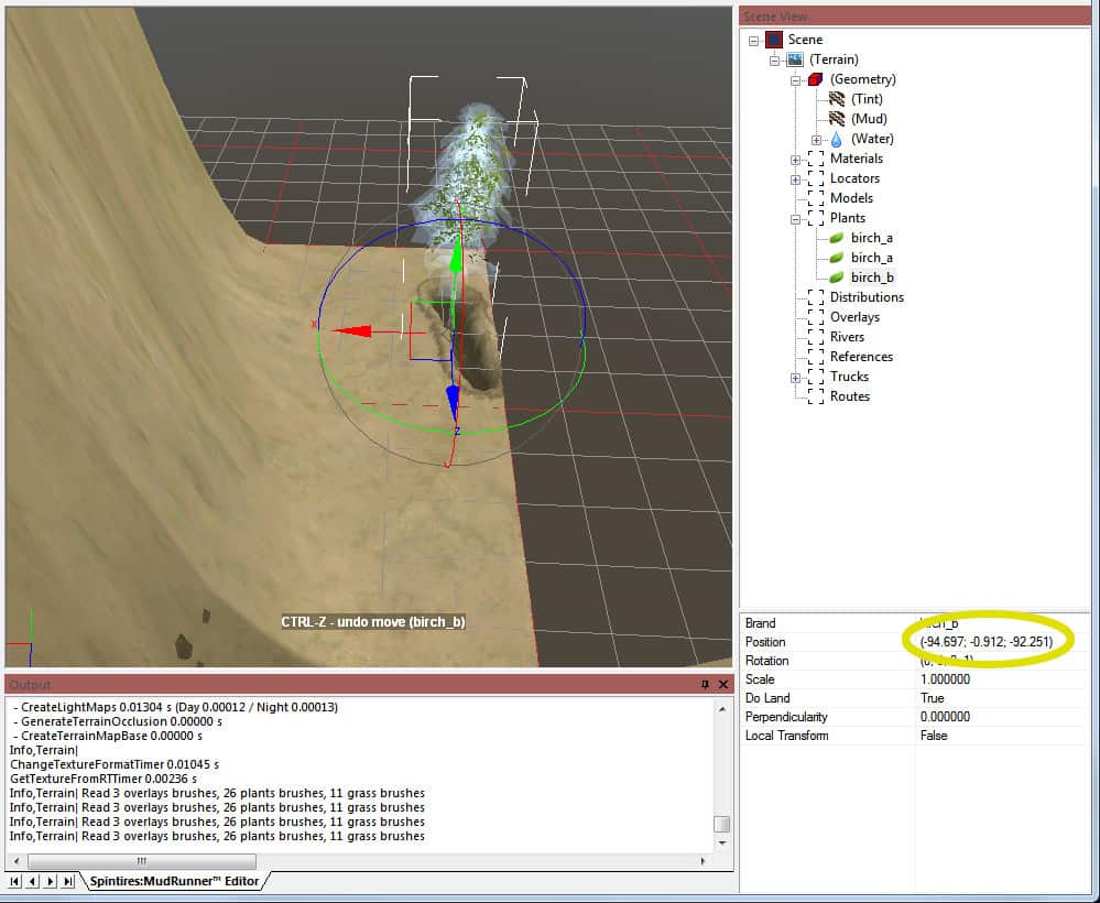
There are rumors of a mod that can change the maximum height, but this discussion will stick to the vanilla editor.
Object coordinates are effectively unbounded. The X and Z coordinates can be beyond the edges of the map, but an object won’t be drawn if its coordinates are outside the map boundaries, even if some portions of the object would extend into the map’s edge.
The Y coordinate can be less than 0 (for an object sunken in the ground) or greater than 64 (for floating objects).
Terrain Block Coordinates
When you left click on the terrain, you select a terrain block. This block is 16 meters on a side (X and Z) and is however tall (Y) the terrain is within that block. The terrain block is labeled with coordinates in (X, Z) format, with (0, 0) being the southwest corner of the map.
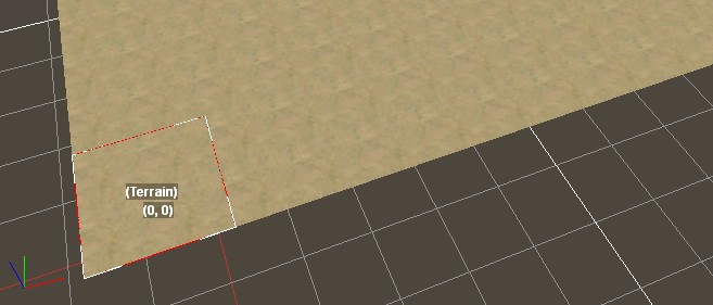
You may have noticed that the terrain block coordinates are overlaid on the map while editing with the tint tool. An explanation of where these come from is in the “Hand Edit a TGA Bitmap” section.
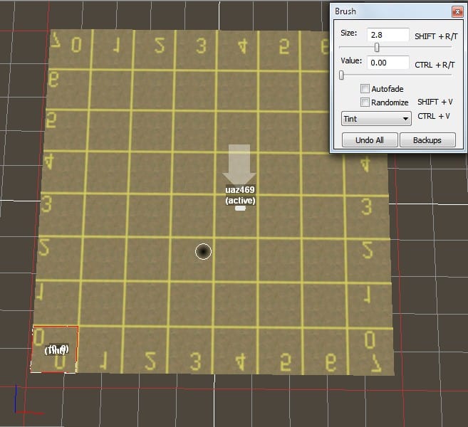
You will occasionally see terrain compilation warnings that specify the location of the problem with terrain block coordinates.

The map size is specified in specified in the map’s XML file as a count of terrain blocks in each direction. E.g.
<Terrain NumBlocksX="8" NumBlocksZ="8">
...
</Terrain>
Bitmap Coordinates
The editor tracks the shape and attributes of the terrain using bitmaps. By common convention, pixels within bitmaps are numbered starting with (0,0) in the upper left and increasing to the right and down. However, the MudRunner Editor chooses to map those increasing bitmap coordinates in the same direction as increasing object coordinates, which means that the Z coordinate increases in the northerly direction while progressing down the bitmap. I.e. the bitmap appears upside down when viewed on the map. You can see this effect in the terrain block numbers overlaid on the map in the example above.
Orientation Coordinate Systems
Not only do objects have a position, they also have an orientation. This section describes the orientation values in detail.
2-D Orientation Coordinates in the Editor
For an object that can rotate only in two dimensions (in a single plane), the editor displays its orientation as a pair of values in (X; Z) format.
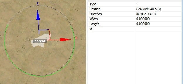
These two values represent a normalized unit vector specifying how close to the X vector the object points vs. how close to the Y vector it points. The length of the direction vector doesn’t matter, so the editor normalizes it to unit length (1 meter).
When the object is initially created, it initially points directly east. In other words, it points entirely along the X axis and not at all along the Y axis, so its direction vector is (1; 0).
For the example [locator] in the screenshot above, the direction vector is (0.912; 0.411). This means that it points mostly east, and a little bit north. Note the normalized unit vector: 0.912² + 0.411² = 1.
Negative values in the direction vector means that the object points some amount to the west or south.
2-D Orientation Coordinates in the XML File
The editor saves 2-D orientation coordinates in the XML file in the same format as it displays in the editor. E.g.
<Locator Org="(-24.709; -40.527)" Dir="(0.912; 0.411)" Id="" />
If an object has the default (initial) direction, the editor will often omit it from the XML file. So if you see a 2-D object in the XML file without a direction, assume (1; 0).
If you directly modify the values in the direction vector in either the editor or the XML file, you could create a vector that is not normalized to unit length. However, it still specifies a valid direction and behaves as such. The editor will preserve the non-normalized values though saves and loads of the XML file. Only when you rotate the object through the main view interface will the editor recalculate a normalized direction vector.
3-D Orientation Coordinates in the Editor
For objects that can rotate freely in three dimensions, the editor displays its orientation as a quaternion with four values. Orientation quaternions are outside the scope of this documentation, but you can find plenty of documentation on the web.
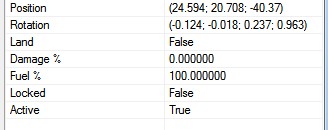
3-D Orientation Coordinates in the XML File
Unlike what is displayed in the editor, a 3-D object’s orientation is saved in the XML file as a pair of normalized 3-D vectors. The names used for these vectors vary for different object types, but they are typically called “Dir” and “Up”.
The screenshots below show the same view of a tilted stop sign with two coordinate axes superimposed. The left image shows the X, Y, and Z axes relative to the map (global space). The right image shows the X, Y, and Z axes on which the object was created (local space). These screenshots will be the reference for the following discussion.
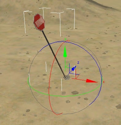
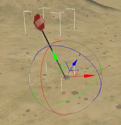
When the object is initially created, its orientation is precisely aligned with the global coordinates. The direction of its Z axis therefore points entirely along the global Z axis and not at all in the direction of the global X or Y axes. Thus, its direction is (0; 0; 1). SInce this direction is the default, the editor will often omit it from the XML file. So if you see a 3-D object in the XML file without a direction, assume (0; 0; 1).
If the object is rotated or tilted, its local Z axis will point along some combination of the global X, Y, and Z axes. For the stop sign example, its direction is (0.061; 0.277; 0.959). Its local Z axis points mostly in the direction of the global Z axis, but also a little bit in the positive direction of the global X and Y axes (east and north). Note the normalized unit vector: 0.061² + 0.277² + 0.959² = 1.
The 3-D direction vector indicates the direction of the local Z axis relative to the global coordinate space, but the object can rotate freely around its Z axis without changing this vector. More information is required to fix the object to a single orientation. The XML file includes this extra information as the “Up” vector. It is determined in the same way as the direction vector, but using the local Y axis instead of the local Z axis.
For the stop sign example, its “Up” is (-0.303; 0.921; -0.246). Its local Y axis points mostly in the direction of the global Y axis (up), but also a little bit west and south.
The default “Up” vector is (0; 1; 0). Many objects (such as houses and stop signs) will be rotated in the ground plane without being tilted. An object whose Y axis points directly up may have its Up vector omitted from the XML file.
It is possible to modify the Up vector to be inconsistent with the Dir vector. In that case, the editor will use the given Dir vector and modify the Up vector to be consistent. However, the editor will preserve the inconsistent values though saves and loads of the XML file. Only when you rotate the object through the main view interface will the editor recalculate and save a consistent Up vector.
Hand Edit a TGA Bitmap
You can edit the various TGA files with your bitmap editor of choice. Using the MudRunner Editor to paint directly on the terrain while all other terrain features are visible is very convenient, but sometimes you might want the power of an application built specifically for bitmap manipulation. (I use Gimp.)
If you’ve configured the path to your texture editor in the MudRunner Editor settings, you could theoretically double-click a TGA file in the File View to open the file in your texture editor. You would first need to Show All Files to expose the prebuild directory and your map’s bitmap subdirectory. However, my testing indicates that the MudRunner Editor doesn’t correctly handle spaces in the path to the texture file when starting the external texture editor. This is a problem since the path will typically contain directories such as “Program Files (x86)” or “Spintires Mudrunner – Editor”. For this reason, I instead open the directory in Windows Explorer and manually start my texture editor from there.
When editing a bitmap, remember that MudRunner’s coordinate system puts south at the top of each bitmap. I.e. the bitmap is flipped upside down when it is used by the MudRunner Editor and game.
Edit the Color Channels
All of the editor’s TGA files use the common format of 8-bits per channel for red, green, and blue, but no more than two of those channels hold useful data per bitmap. The MudRunner Editor initializes the unused channel(s) with a numbered grid to help keep you oriented. You may have noticed this grid when you selected the tint tool in the MudRunner Editor.
You will probably want a bitmap editor that allows you to draw into only one color channel at a time while leaving the other channels unchanged. The below screenshot from Gimp shows the channel selection toolbox with just the blue channel selected. (The eye icon for each channel means that all channels remain visible, however.)
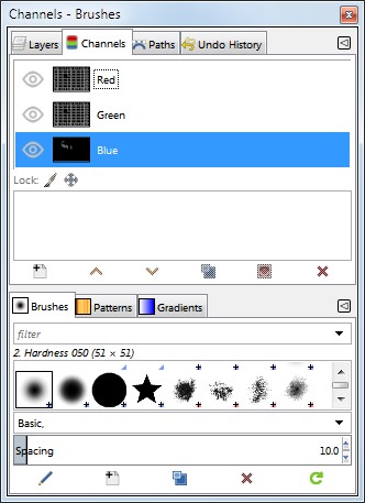
When you are done editing the TGA in your favorite bitmap editor, save (or export) it back to the game directory in place of the MudRunner Editor’s file. Then select Rebuild Terrain from the context menu to view the terrain with your changes.
Using a Different File Type
Although the MudRunner Editor expects the bitmap file to have a .tga extension, it uses a bitmap library that can read a variety of formats. For example, I have verified that it can read bitmaps in PNG, DDS, or even JPG format. If producing a TGA file is inconvenient, you can instead try creating your bitmap in some other common format, then rename its extension to .tga and see if the editor will read it. (Warning: if the editor fails to read a critical TGA file, it will hang and need to be manually killed.)
The bitmap can also use a different number of bits of color information per pixel. The default TGA files have 8 bits per channel in RGB format (a total of 24 bits per pixel). The editor also accepts bitmaps with 16 bits per channel and/or in RGBA format (32, 48, or 64 bits per pixel). It does not appear to accept bitmaps in grayscale format (with only one channel).
Using a Different Bitmap Size
For each bitmap property, the MudRunner Editor uses a number of pixels in each terrain block that was prechosen to result in natural looking visuals. These pixels are distributed from edge to edge of the terrain block in each dimension, and the pixels at each edge are shared with the adjacent terrain block. If R pixels are distributed across one dimension of a terrain block, and the map is N terrain blocks wide, then the total width of the bitmap would be ((R-1)*N)+1. The calculation for height is the same where R is the same value but N may be different for a rectangular map.
The MudRunner Editor uses the following values for R:
- Tint (_tint.tga): R = 25.
- Water (_water.tga): R= 32.
- Water→Mud (_water_mud.tga): R = 4.
- Materials (mtrl_*.tga): R = 25.
- Distributions (dstr_*.tga): R = 25.
Remembering that there are 16 meters per terrain block, a 128 x 128 meter map would have a _tint.tga bitmap with dimensions (25-1)*(128/16)+1 = 193 x 193.
If you supply the MudRunner editor with a bitmap of a different size, the editor will stretch or squash it to its desired size. This feature can be handy when importing terrain data from some other source. Rather than resizing the bitmap before importing it into the MudRunner editor, just give it the raw file and let it resize it.
If the bitmap in the file is a different size than expected, the MudRunner Editor creates an internal bitmap of the proper size by sampling the pixels that it needs from the file’s bitmap. Effectively, the editor stretches or squashes the bitmap so that the width and height of the bitmap match the X and Z dimensions expected by the editor. If a desired pixel falls between pixels in the stretched/squashed bitmap, the editor interpolates between the centers of the nearest neighboring pixels in the bitmap.
If the bitmap in the file is small, then the editor’s desired pixel may be between the map’s edge and the center of the first (stretched) bitmap pixel. In that case, the editor interpolates between the centers of the bitmap pixels at opposite edges of the bitmap (as if the bitmap were tiled across the boundary).
The smallest bitmap that the MudRunner Editor can read appears to be 2×3 or 3×2. 2×2 causes it to fail and hang. The below images show a (zoomed-in) 3×2 tint bitmap in GIMP and the resulting tinting in the editor. This highlights the interpolation between pixels in the interior and at the boundaries of the bitmap. Remember that the image gets flipped upside down by the editor, and blue pixels become a dark tint, and black pixels become a light tint.
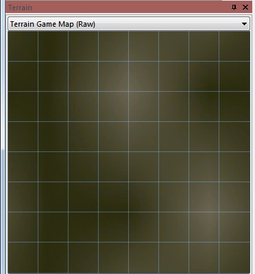
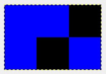
Hand Edit the DDS Height Bitmap
You can edit the terrain height in your bitmap editor of choice. The section above for TGA bitmaps introduces many concepts that are the same for the DDS height bitmap. I recommend that you become read that section before this one.
The MudRunner Editor stores the terrain height in _height.dds in R16F format. DDS isn’t natively supported by many image tools, and R16F isn’t well supported even by some DDS tools. However, I can tell you some techniques that are a bit gross, but work.
Convert the DDS File to 16-bit PNG
The first step is to convert _height.dds to a more standard image format.
An online converter I’ve found that handles 16-bit channels is here:
https://online-converting.com/image/convert2png/
When using this converter, make sure to set the “Color” to “48 True color, RGB)” to get 16-bit channels in the output.
The result is a PNG file with 16-bit channels that can be loaded into a 16-bit-per-channel bitmap editor such as Gimp (version 2.9 or above).
Convert the DDS File to 8-bit PNG
Some MudRunner guides will tell you that it is perfectly fine to convert to a format with 8-bit channels, but this is a big lie. The maximum value in 8 bits is 255, which means that the maximum 64 meter map height gets divided into 64/255 = 0.25 meter steps. It looks fine for perfectly flat ground, and it looks fine for impassibly steep terrain, but a smooth slope gets converted into 25 cm (~1 foot) steps. It’s bad.
But if 8 bits per channel is all that you can handle, you can use another conversion tool such as readDXT. readDXT is available in the “DDS Utilities” package from nVidia.
Edit the Bitmap
Continuing the table from the TGA section previously:
- Height (_height.dds): R = 25.
Depending on which converter tool you used, you may end up with a grey-scale image. However, only the red channel will be used by the MudRunner Editor. If you like, you can copy the grid pattern from one of the TGA files into the green or blue channels of the height bitmap.
While editing, remember that the game engine cannot handle height variation of more than 16 meters in one terrain block. If you exceed the limit, the MudRunner Editor will output heightmap errors and will compress the terrain to fit.
Make sure to select 16-bit channels when exporting your edited image. If you are using Gimp 2.9+, it should do this automatically when exporting to PNG.
Convert the PNG to DDS
As discussed in the TGA section previously, the MudRunner Editor can convert from a different file format. All you have to do is rename your bitmap file to _height.dds. Then choose Rebuild Terrain from the context menu. You will get an error that you can ignore.
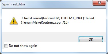
To prevent the error from recurring, you want the MudRunner Editor to write the height information back into _height.dds in proper DDS format. Do this by making any height change (such as by painting any height with value 0.5).
Hand Edit the Mud File
Short answer: you can’t.
The mud file is in a non-standard format. A cursory look indicates that it includes multiple bitmaps in DDS format. These are most likely a sparse representation of the mud so that space is not wasted on non-muddy areas.
At this time I have not looked into whether it is possible to edit the mud file by hand.
If the mud were editable by hand, care would need to be taken to edit the different aspects of the mud in a consistent fashion, e.g. the depth of the mud, its softness, its height above the terrain, etc.
Hand Edit a Material Bitmap
The mtrl_*.tga bitmap records the opacity and blend of “Grass” and “Dirt” for each material.
The “Grass”/”Dirt” blend is in the green channel. Low values indicate more “Grass”; high values indicate more “Dirt”.
The opacity is in the blue channel. The material is opaque for the entire terrain block if the blue channel is any non-zero value in the center pixel of the terrain block.
The red channel is unused.
Hand Edit a Distribution Bitmap
The dstr_*.tga bitmap records the density and scale of distributed plants.
The density is in the red channel. Low values indicate fewer plants; high values indicate more plants.
The scale is in the green channel. Low values indicate smaller plants; high values indicate larger plants.
The blue channel is unused.
— Appendix C: Create Custom Features —
The following sections describe how to customize the MudRunner features such as materials, distributions, and models. This includes simple alterations to the XML for each feature to change its behavior as well as more complex changes to shapes and textures.
Remember that MudRunner’s XML is generally sensitive to case, so make sure to use uppercase and lowercase exactly as specified.
The MudRunner Editor rereads most of your custom files each time you Rebuild Terrain, so experimentation can be fairly quick. The exceptions are noted where the file is described.
Each section points to where you can find the built-in game assets so that you can study their techniques and perhaps copy and modify them. You may notice that the XML for some built-in features accidentally specifies two different values for the same property. Only the first value gets used.
This guide describes all known XML tags and properties and what they do. It also describes any other asset files that you can create or modify.
If a property is required to be specified, it is shown as part of the XML summary. Otherwise, it is described as a property but is not included in the XML summary.
XML Property Values
The following terms are used when describing XML property values.
“{value}” is a numeric value. In many cases it can be negative or positive, and almost all values can be decimal (e.g. “0.1”). Most dimensional values are specified in meters, and most angle values are specified in degrees (with a few exceptions that are specified in radians). Mass is generally in kilograms, and force is in newtons.
“{filename}” is a filename, possibly with some directory structure included.
“{name}” is a generic string.
“{color}” is a color specification, described in the Color section below.
Other terms in braces that describe property values should be obvious from context.
Some properties allow only the values of “true” or “false”. For these binary properties, the property introduction shows only the non-default value. The opposite value is implied as the default, but because it is the default, the property never needs to be explicitly specified with that value. In many cases, this guide documents only the non-default property value. The default behavior is implied.
Filenames and Mod Boundaries
The MudRunner Editor will freely use custom assets from all of your mod directories, which can get confusing if you’ve copied the same asset to multiple mod directories. (And particularly if you’ve modified an asset differently in different directories.) Experimentation suggests that for at least some features, having multiple custom assets with the same name leaves you with a mix of properties from them. This also means that you can’t change the properties of built-in assets, or at least not predictably.
Unlike the editor, the MudRunner game requires that all custom assets be in the same mod directory as the map (unless you start the map from the proving ground). This is a useful check when using testing methods 2 or 3 prior to publishing.
In order to keep the game happy and to prevent confusion in the editor, I recommend that you include the mod name in the filename of all of your custom assets. You can abbreviate the mod name of course, as long as your abbreviations are unique.
I also like to start my names with an underscore so that they are grouped together at the beginning of any list presented by the MudRunner Editor.
Mesh and Texture Caches
The MudRunner Editor and MudRunner game each keep caches of optimized mesh and texture information. The mesh cache combines data from a model’s .x file and associated mesh XML file (but not its class XML file). The texture cache contains data for a texture bitmap used for any purpose (e.g. by a custom material, model, grass, etc.)
The editor’s caches for your custom features are here:
%appdata%/SpinTiresEditor/MeshCache

%appdata%/SpinTiresEditor/TextureCache
The game’s caches for your custom features are here:
%appdata%/SpinTires MudRunner/MeshCache

%appdata%/SpinTires MudRunner/TextureCache
In general, MudRunner notices any changes to the original files and updates its cached copy automatically. In the editor, you’ll see a line in the log that the file is out of date, which is a bit deceptive. The message actually means that the cache is out of date and is being updated from the file.
![]()
The editor reloads the mesh files (and updates the cache) whenever you Rebuild Terrain. It won’t reload textures that are already in memory, though. To reload a texture (and update the cache), close and reopen your map.
In most cases you won’t have to worry about the cached copies. However, the cache may bite you if you update the file without advancing its time stamp. The most likely scenario is when you restore an older version of a file, meaning its time stamp is now older than before. Since MudRunner sees that the cached file is newer, it thinks that the cache doesn’t need to be updated. If this happens, just clear the file from the cache (or erase the cache itself) to force a refresh.
MudRunner also continues to use a cached file if the original file is deleted. In fact, if you refer to a missing file, the editor or game will use the cached file without complaint, so be careful.
BTW, don’t delete the MeshCache.zip or TextureCache.zip files in the MudRunner editor or game application directories. These are the master copies of the game assets and by definition cannot be out of date.
Texture Optimizations
When the MudRunner Editor reads a custom texture file, it converts the file to DDS format (if necessary) and optimizes it for use by the game engine before caching it. If the texture file you supplied had its own directory hierarchy (and it should), the editor flattens that out, replacing slashes with underscores. E.g. tiles/example__d_a.tga gets turned into tiles_example__d_a.dds in the texture cache.
You can reverse this process to use the built-in assets in TextureCache.zip. E.g. to use “models_concrete_fence__d.dds”, edit your XML file to refer to “models/concrete_fence__d.dds”. This file doesn’t actually exist, but as discussed above, MudRunner is happy to use its cached file when it can’t find the original.
When you publish your map to the Steam workshop, the MudRunner Editor forces a refresh of the texture cache for all texture files it finds in your mod. It then publishes these cached files, rather than your original files. This means that you never have to worry about the format of your files, nor do you need to optimize them for the game engine yourself. The editor does the work for you as long as you follow the naming conventions below.
Texture File Names
The optimizations that the editor applies to the cached DDS file depend on the end of the filename (not including the file type extension):
If the file ends with __d_a, it is treated as a diffuse texture with an alpha channel. It is compressed accordingly, and mipmaps are generated automatically.
If the file ends with __d, it is treated as a diffuse texture. It is handled the same as __d_a above, but without the alpha channel. (If a semi-transparent texture ends with __d, it is composited over a black background to create the RGB image without alpha. That is unlikely to be what you want.)
If the file ends with __s_d, it is treated as a specular map. It is compressed to a 1-channel texture, using only the red channel from the original image, and mipmaps are generated automatically.
If the file ends with __n_d, it is treated as a normal map. It is compressed accordingly, and mipmaps are generated automatically.
If the file ends with __uncmp or if the filename does not end with __*, it is converted to DDS but no optimizations are applied and mipmaps are not generated. This works, but it isn’t optimal. Try to remember to name your texture files appropriately.
Cache Leaking between Mods
Each mod is supposed to be self contained. The editor doesn’t check this, but the game does for any of the testing techniques that go through the normal map selection screen. (The game doesn’t enforce mod boundaries when you start a level from the proving ground.)
However, a cached mesh or texture can foil the module containment checks. To avoid this, I re-iterate the recommendation from the previous section that you give all of your mod files a name unique to that mod.
As an additional precaution, I recommend that you point to only one mod at a time in the game’s Config.xml file. The game clears its caches whenever the Config.xml file changes, so you can be sure that it never uses a cached file from a different mod.
Tags can be commented out of the Config.xml file using “<!–” and “–>”:
<MediaPath Path="c:/Program Files (x86)/Steam/SteamApps/common/Spintires Mudrunner - Editor/Media/_mods/5e5c745c" /> <!--<MediaPath Path="c:/Program Files (x86)/Steam/SteamApps/common/Spintires Mudrunner - Editor/Media/normal/5d80fa0a" />--> <!--<MediaPath Path="c:/Program Files (x86)/Steam/SteamApps/common/Spintires Mudrunner - Editor/Media/normal/5e46c670" />-->
Colors
Although most colors in MudRunner come from textures, pure colors are allowed or required in a few places when creating custom assets. This section describes how to specify a color for MudRunner.
Color Space
MudRunner allows you to specify colors in either of two color spaces.
Uncorrected colors represent a linear range of physical light intensity. These are represented as “({R}; {G}; {B})”. The normal range for the R, G, and B values is 0 to 255. E.g. “(128; 128; 128)” represents a gray value with half as much light as full white.

Gamma-corrected colors appear to have a linear range of perceptual intensity to human vision. These have a “g” in front of the color specification: “g({R}; {G}; {B})”. E.g. “g(128; 128; 128)” represents a gray value that looks half as bright as full white. This is the color space used by textures, so an image with gray pixels of 128, 128, 128 matches MudRunner’s color “g(128; 128; 128)”.

Note that full black and full white are the same in both color spaces, but the intermediate values are spaced differently.
Values greater than 255 can be used to represent a color brighter than full intensity. The difference can’t be perceived in full light, but it makes a difference when the color is muted by shadow. But bright colors in general look very unnatural, so use them with care.
Color Multiplier
You can add a light intensity multiplier to any color. E.g. “(128; 128; 128) x 2.0” is the same as “(256; 256; 256)”. This can be used to quickly brighten or darken a color without needing to recalculate individual R/G/B values.
The multiplier is always with respect to physical light intensity, even if a gamma-corrected color is specified. E.g. “g(128; 128; 128) x 2.0” equates to roughly “g(175; 175; 175)”.
Alpha
A color can also be specified as “({R}; {G}; {B}; {A})” or “g({R}; {G}; {B}; {A})”, where A represents alpha. An alpha value of 0 is fully transparent. An alpha value of 255 is fully opaque. The default value is 255 when A is left unspecified.
The alpha value is not gamma corrected, so 128 is half-transparent whether or not the a gamma-corrected color is specified. The color multiplier also has no effect on the alpha value.
Color Math
Occasionally colors are combined together via a mathematical formula. The math treats each R/G/B light intensity value separately, and the intensity range is scaled so that full intensity (255) is scaled to 1.0 for the computation. E.g. multiplying a color by (511; 255; 0) causes the amount of red to be doubled, the amount of green is left unchanged, and all blue is removed from the color.
Alpha values are never included in color math.
Custom River Water
The standard water colors for rivers are blue, brown, dark, and green, but you can also make your own water.
Examples in Media/classes/waters/*.xml
Your file goes in {mod directory}/classes/waters/{name}.xml
<WaterType

ColorDiffuse="{color}"

ColorFoam="{color}"

ColorReflected="{color}"

ColorRefraction="{color}"

ColorScatter="{color}"

ColorSubstance="{color}"

OpacityDepth="{value}"

OpacityBias="{value}"

TintDepth="{value}"

TintBias="{value}"

/>
Because the editor uses a simplified lighting model, water is displayed very differently in the editor vs. in the game. This section tries to describe in detail the effect of the properties on how water looks in the game. I also briefly describe any differences in how it looks in the editor, mostly so that you don’t get fooled by the editor display.
ColorDiffuse="{color}"
ColorDiffuse specifies the color of the water. This color is also used to draw the water on the navigation map.
ColorDiffuse has the same effect in the editor.
All example images for water colors use a bright green color to highlight the effect of the property being described.
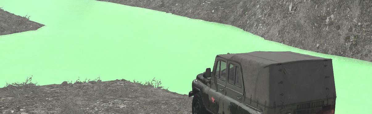
ColorFoam="{color}"
ColorFoam specifies the color of the foam. This affects not just foam drawn with the map editor, but also foam dynamically created as the player’s truck splashes through water. The foam still has white highlights as usual, regardless of ColorFoam. Foam is not drawn on the navigation map.
ColorFoam has the same effect in the editor.
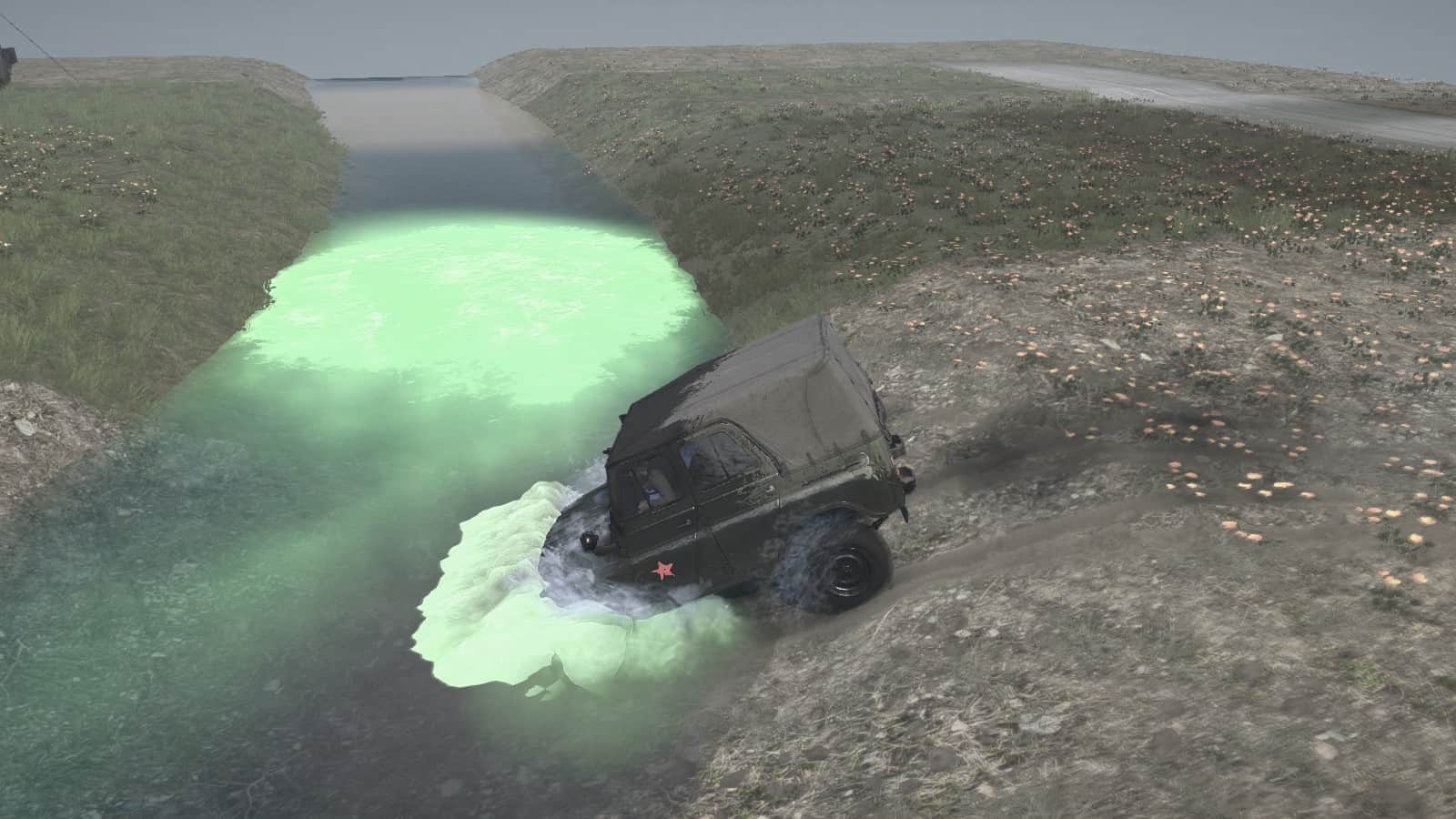
ColorReflected="{color}"
ColorReflected alters the color of self occlusion close to the water, as if light is reflecting off the water. Requires Rebuild Terrain to take effect. Has an effect only during the day. Does not affect regular shadows. The effect falls off rapidly with horizontal distance and is gone within 1-2 meters of the water’s edge. The effect doesn’t fall off at all with height. The effect is more obvious in the editor than in the game.
The images below show the change in reflected color at a sharp boundary between rivers with different colors.
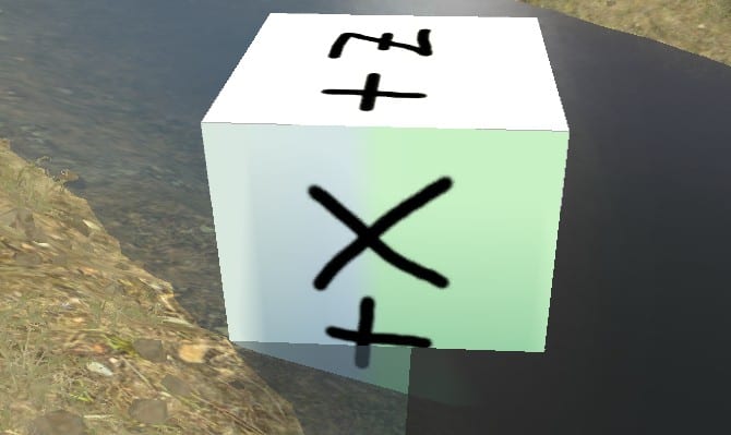
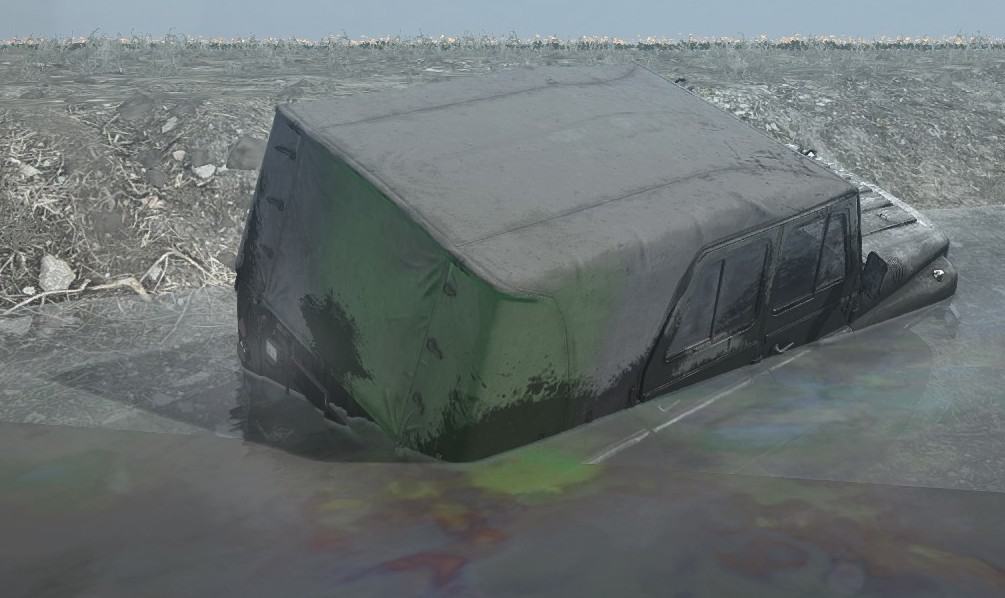
ColorRefraction="{color}"
ColorRefraction is a multiplier for the color of anything seen below the water. E.g. white objects become this color, while black objects are left unchanged. Dark ColorRefraction colors can change the perceived opacity of the water.
ColorRefraction has no effect in the editor.
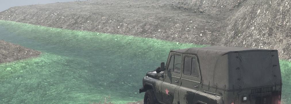
ColorScatter="{color}"
ColorScatter appears to have no effect in the game or editor. It is still a required property, however.
ColorSubstance="{color}"
ColorSubstance specifies the color of water thrown into the air by the truck. Unlike the related ColorFoam, ColorSubstance color is strictly added to existing colors in the scene, so ColorSubstance=”(0;0;0)” causes the thrown water to be invisible.
ColorSubstance has no effect in the editor, of course.
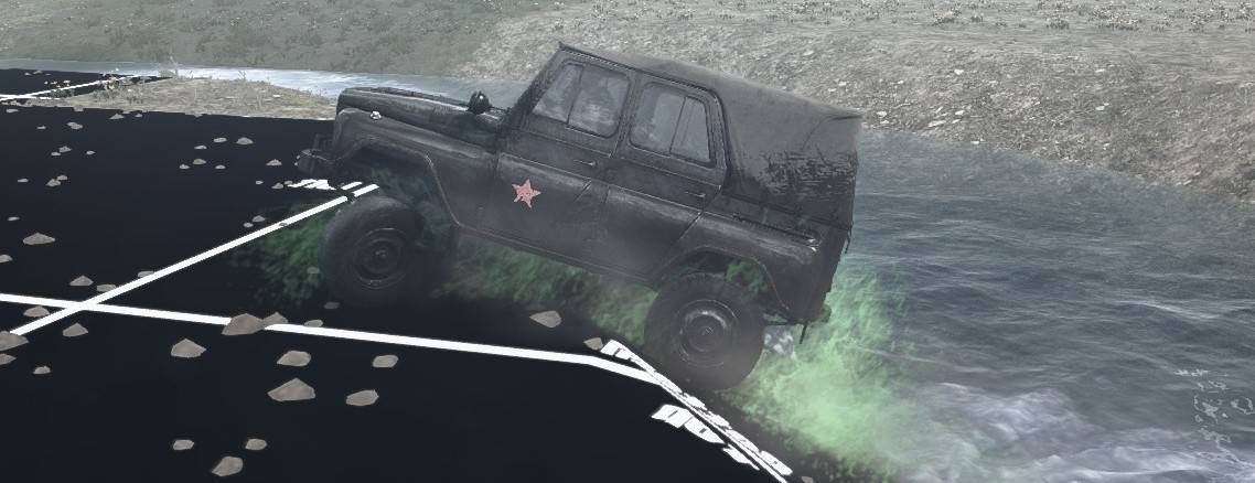
OpacityDepth="{value}"
OpacityDepth specifies the depth at which the water becomes fully opaque. It also becomes opaque at long angles that are less deep than OpacityDepth. However, you can still see a further length through water than OpacityDepth when viewing at an angle. A value of 0.0 causes the water to be fully opaque at all depths.
OpacityDepth has no effect in the editor.
The following images with OpacityBias=”0.0″ have OpacityDepth=”0.3″ on the left and OpacityDepth=”0.0″ on the right.
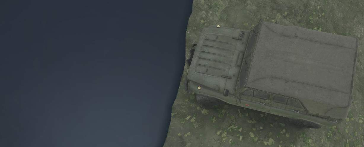
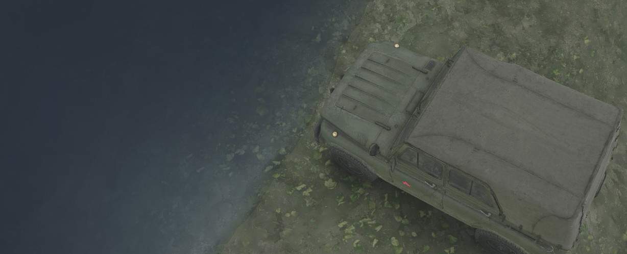
OpacityBias="{value}"
OpacityBias specifies how quickly the water becomes opaque. There are no known limits to the value, but the range of effective values appears to be 0.0 to 1.0. A value of 0.0 causes the opacity to increase linearly with depth. Higher values cause the opacity to increase more quickly at first, although not becoming fully opaque until the OpacityDepth. A value of 1.0 causes the water to be fully opaque at all depths.
Since the editor ignores OpacityDepth, OpacityBias has a fudged behavior in the editor. The range of effective values appears to be -1.0 to 0.6. -1.0 is fully transparent, although foam remains visible. 0.6 is fully opaque.
The following images with OpacityDepth=”0.3″ have OpacityBias=”0.0″ on the left and OpacityBias=”0.8″ on the right.

TintDepth="{value}"

TintBias="{value}"
I am unable to determine what effect these have. TintDepth=”0″ causes the water to become weirdly transparent in certain terrain blocks and in polygonal chunks around the splashing truck and around old truck ruts, which leads me to believe these properties have something to do with the river mud color and/or oily sheen, but I can’t figure out what.
Custom Material
Material XML
Built-in material XML files are in Media/classes/terrains/*.xml
Put your material XML files in {mod directory}/classes/terrains/*.xml
<MaterialType

Texture="{filename}"

{properties}

/>
Keep in mind that a materials tile blends two different materials with variable intensity. Therefore, the various properties for each material are blended as well. The intensity of a material varies from 0% (where it is not present at all) to 100% (where no other material is present at all). For each binary property that must be either True or False, there is an intensity threshold where the property is used from one material and not the other. All of my intensity thresholds are best estimates.
The XML properties are as follows.
GenerateDust="true"
A truck throws dust into the air when it crosses the terrain. GenerateDust takes effect at 1% intensity. I.e. if the material is at all present, it starts generating dust.
IsThickGrass="true"
Excludes grasses listed in Group A in the Materials Reference section. Excluded grasses have NotAtThickGrass=”true”, but see the caveat for the NotAtThickGrass property in the Custom Grass Distribution Brush section.
The idea here is that the material already has thick grass on the ground, so adding more 3-D effects on the ground isn’t useful. IsThickGrass takes effect at 75% intensity.
NoGrass="true"
Excluded grasses do not have IgnoreNoGrass=”true”, but see the caveat for the IgnoreNoGrass property in the Grass Class XML (Distribution) section. Excluded plants do have CheckNoGrass=”true” as described in the Plant Class XML (PlantBrand) section. The built-in grasses and plants that are excluded are listed in Group B in the Materials Reference section.
The idea is possibly that certain materials simply aren’t fertile enough to support most plant life. NoGrass takes effect at 33% intensity.
GrassBrush="{name}"
Names a distribution brush to automatically apply to the material. The brush must be from the set of grass brushes. The brush is applied the same as a distribution with density equal to intensity and with 100% random scale. If NoGrass=”true” or IsThickGrass=”true” and the selected GrassBrush is excluded, then the GrassBrush is ignored the same way it would be in a separate distribution.
IsExtrudable="false"
Prevents the material from deforming into ruts under repeated truck traffic. It also causes the truck to generate dust when driven across the material, even if GenerateDust=”false”.
If IsExtrudable=”true” (or is left undefined), the material deforms into ruts, and a truck driving across the material throws dirt clods from its tires. In other words, you can have dust, or clods, or both, but never neither.
IsExtrudable=”true” allows ruts only at 100% intensity, but throws dirt clods at 1% intensity.
WheelTracks="0"
Prevents the game engine from drawing tire tracks on the material during normal driving conditions. This seems like it should be a true/false property, but for some reason it isn’t. Any non-zero value (even “false”) causes wheel tracks to be drawn. WheelTracks fade in or out in proportion to the material intensity.

Muddy wheels always leave tracks on materials. There is no equivalent to the IsWheelTracks property used by models.

IsGameAsphalt="true"
Unknown purpose.
Texture="{filename}"
Specifies the path to the texture file.
Built-in material textures are in TextureCache.zip/tiles_*.dds
Put your material textures in {mod directory}/textures/tiles/
I recommend that the filename be in the form “tiles/{name}__d_a.{ext}”. Putting your texture file in textures/tiles replicates the directory hierarchy used by the built-in materials. Using the “__d_a” suffix on the filename ensures that the texture is optimized for distribution. Hopefully you’ve read the “Texture Caches” section of this guide so that you’re aware of the behind-the-scenes manipulation of your texture file.
Material Texture
The intensity of the texture is proportional to the material intensity and to the texture opacity in the alpha channel. I.e. making the texture more opaque makes it retain a stronger intensity in the blend even if the material intensity is lower. However, at 100% material intensity the texture is always completely opaque, regardless of the alpha value in the texture.
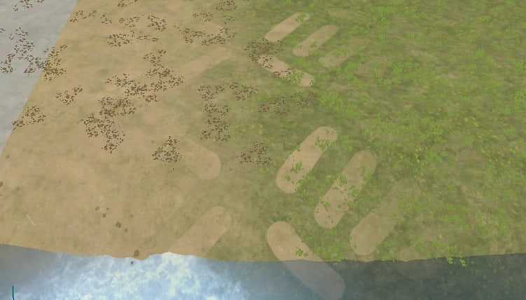
Custom Plant Distribution Brush
Distribution brushes are described in Media/prebuild/common/brushes.xml
There is no separate file for your own custom brushes. You simply edit the master brushes.xml file. The MudRunner Editor uses the distribution brushes to distribute plants and grasses into the compiled files. The brushes are never used directly by the game engine, so you don’t have to package your custom brushes in with your mod.
Warning: An update to the MudRunner Editor may wipe out your changes to the brushes.xml file. Make sure to keep a copy! (I tried creating my own brushes.xml file in my mod directory, but it doesn’t get used.)
There are multiple types of brushes in the XML file. We’ll only look at brushes in the tag here. A plant brush can include one or more plants and can also include the contents of a grass brush (described in the next section).
<Plants>

<{PlantBrushName} PlantsPerBlock="{value}" {brush properties} >

<PlantType

Brand="{plant_name}"

{plant properties}

/>

...

</{PlantBrushName}>

...

</Plants>
Brush Properties
FlatThreshold="{value}"
Specifies the maximum terrain steepness at which the distribution is applied (e.g. to avoid plants on cliff faces). The default is 1.0 for no restrictions. The minimum allowed value is 0.01. I’m not sure exactly what this value represents. Even a value of 0.01 allows plants to be distributed on quite steep terrain, although not quite as many as would otherwise be placed.
LinkedGrassBrush
Optional. Specifies the name of a grass brush that is used together with the plant brush.
PlantsPerBlock="{value}"
Specifies the number of plants per terrain block. The value is rounded down to the nearest multiple of 4. It counts all types of plants in the brush together, but it does not count plants in the linked grass brush, and it doesn’t count plants used in a different distribution (even one using the same brush). The density of plants is also limited by the properties of the plants themselves, described below.
One or more PlantType sections describe the properties for each plant used by the brush.
Plant Properties
Brand="{plant_name}"
Specifies the name of the plant. Each plant comes with its properties, some of which affect its distribution. These effects are described below.
MinMapScale="{value}"

MaxMapScale="{value}"
Specifies the minimum and maximum values (0.0 to 1.0) in the distribution bitmap’s scale channel at which the plant appears. Setting these properties means that when the distribution has a biased scale, the choice of plant types is biased as well. MinMapScale defaults to 0.0, and MaxMapScale defaults to 1.0. Depending on the values in the scale channel, these parameters may mean that the plant type is not distributed at all, or even that no plants are distributed by the brush.
MinSize="{value}"

MaxSize="{value}"
Specifies the minimum and maximum scale for the plant (0.25 to 4.0), which determines the plant’s size. The minimum scale is used at the MinMapScale, and the maximum scale is used at the MaxMapScale. The defaults are 1.0 for both values.
Warning: if the final scale for a plant is 0.25 or less, it will result in an error. Depending on how the bitmap’s scale channel is randomized, this can generate a lot of errors as the plants are distributed.
ScaleRandom="{value}"
Introduces randomness into the plant scale beyond whatever randomness is in the distribution bitmap’s scale channel. After determining the default plant scale based on the scale channel and the MinSize/MaxSize properties, the editor further multiplies the plant’s scale by a random number between (1–value) and (1+value). Warning: if the final scale for a plant is 0.25 or less or is greater than 4.0, it will result in an error. This can generate a lot of errors as the plants are distributed.
Perpendicularity="{value}"
Specifies the fraction (0.0 to 1.0) that the plant is leaned toward ground normal. The default is 0.0, which is vertical. A value of 1.0 causes the plant to stick straight out from the ground, for whatever amount the ground is tilted.
Divergence="{value}"
Specifies the maximum angle (in radians) that the plant’s tilt diverges from the default (based on the Perpendicularity property). The tilt of the plant is randomized between 0 and the specified value.
PlaceOnlyOutsideWater="true"
Prevents the plant from being distributed in water. (Note that a distribution defaults to not placing any plants in water unless it’s Ignore Water property is True.)
PlaceOnlyInWater="true"
Prevents the plant from being distributed on land. Setting PlaceOnlyOutsideWater and PlaceOnlyInWater both to true will prevent the plant from being distributed anywhere.
Plant Properties that Affect Distributions
Each type of plant has its own properties that affect distributions. These are described in the Plant Class XML (PlantBrand) section.
Custom Grass Distribution Brush
This section assumes that you’ve read the previous Custom Plant Distribution Brush section.
A grass brush in the brushes.xml file can include one or more grasses.
<Grass>

<{GrassBrushName} PlantsPerBlock="{value}">

<PlantType Brand="{grass_name}" />

...

</{GrassBrushName}>

...

</Grass>
A grass brush can include one or more grass types. The PlantsPerBlock property is the same as for plant brushes in the previous section. The Brand property is similar, but here it specifies a grass name. There are no optional properties for grass.
When customizing the PlantsPerBlock property, beware to not create so many grasses that it slows down the rendering engine. Having said that, I have no idea how much the current density limits are intended to avoid performance bottlenecks vs. simply creating a pleasing grass distribution.
Grass Properties that Affect Distributions
Each type of grass has its own properties that affect distributions. These are described in the Grass Class XML (Distribution) section.
Custom Road Overlay
Built-in overlay XML files are in Media/classes/overlays/*.xml
Built-in overlay textures are in TextureCache.zip/overlays_*.dds
Put your overlay XML files in {mod directory}/classes/overlays/*.xml
Put your overlay textures in {mod directory}/textures/overlays/
Warnings
Be warned that the MudRunner Editor keeps certain overlay information cached. If you create a new custom overlay while a map is open and then attempt to use the new overlay, you’ll likely get an error dialog followed by a crash.
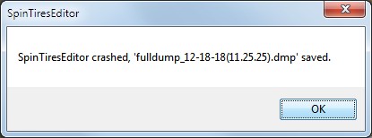
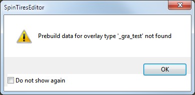
Overlay XML
<OverlayBrand

{game properties}

>

<Prebuild

{prebuild properties}

/>

</OverlayBrand>
Game Properties
Texture="overlays/{filename}"
Specifies the texture for the road overlay. It may include an alpha channel for fading effects. The texture is rendered right side up (not vertically flipped), and the left side of the image corresponds to the “0” point of the road.
The built-in textures are 2048 x 1024. Your texture can be any size and aspect ratio; the texture height is always stretched to the default road width and its width is stretched to twice the default road width. If the mapped road is narrower than the default for the overlay, the texture is cropped to the road width. If the mapped road is wider than the default for the overlay, the texture is tiled to fill the road width. Actually, the road is always drawn slightly wider than specified, so a road of the default width will still display a bit of replication at the edges.
TextureSpecular="overlays/{filename}"
Specifies a specular map. The built-in textures are 1024 x 512.
Be aware that the change in appearance is only visible in the game and not in the editor.
TextureHeight="overlays/{filename}"
Specifies a heightmap. The heightmap causes parts of the texture to be warped as if it were slightly higher or lower when viewed from the current camera angle, but it does not actually change the terrain height. The effect is very small, perhaps an apparent 5 cm difference between the lowest values and the highest values.
Be aware that the change in appearance is only visible in the game and not in the editor.
The built-in heightmap textures are 1024 x 512.
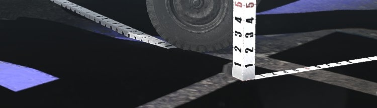
GenerateDust="true"
A truck throws dust into the air when it drives on the overlay.
IsExtrudable="false"
Prevents ruts from forming on the overlay. The default is “true”, but it still takes significant effort to generate ruts of any depth on an extrudable overlay.

WheelTracks="0"
Prevents the game engine from drawing tire tracks on the material during normal driving conditions. This seems like it should be a true/false property, but for some reason it isn’t. Any non-zero value (even “false”) causes wheel tracks to be drawn.
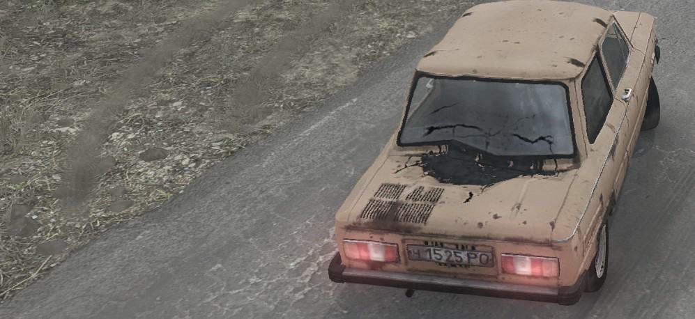
Muddy wheels always leave tracks on roads. There is no equivalent to the IsWheelTracks property used by models.
IsGameAsphalt="true"
Unknown purpose.
IsClampV="true"
Clamps the road width to the default width, so it can’t be scaled in the editor or even in the map’s XML file.
Prebuild Properties
The prebuild properties are used only by the MudRunner Editor. Once the associated features are baked into the compiled files, they are not directly used by the game engine.
Layer="{value}"
Determines the priority of the road over other roads in the same terrain block. A higher value means higher priority. The default value is 0, and the built-in roads use layers 0 to 4. This is one of the few numeric property values that should be an integer, but it can be outside the range of 0 to 4.
DefaultWidth="{value}"
The default width of the road in meters.
MaskPlants="false"
By default, plants are excluded within the width of the road (regardless of transparency). if MaskPlants=”true”, only certain plants are excluded. Excluded grasses do not have IgnoreNoGrass=”true”, but see the caveat for the IgnoreNoGrass property in the Grass Class XML (Distribution) section. Excluded plants do have CheckNoGrass=”true” as described in the Plant Class XML (PlantBrand) section. The built-in grasses and plants that are excluded are listed in Group B in the Materials Reference section.
FlattenPart="{value}"
Determines the fraction of the road width that is flattened if the road is flattened. The default is 0. Most built-in roads set the value to 1. The number can be greater than 1 to flatten a wider area or between 0 and 1 to flatten only part of the road width.
If the road width is scaled differently than the default, the flattened part is also scaled accordingly.
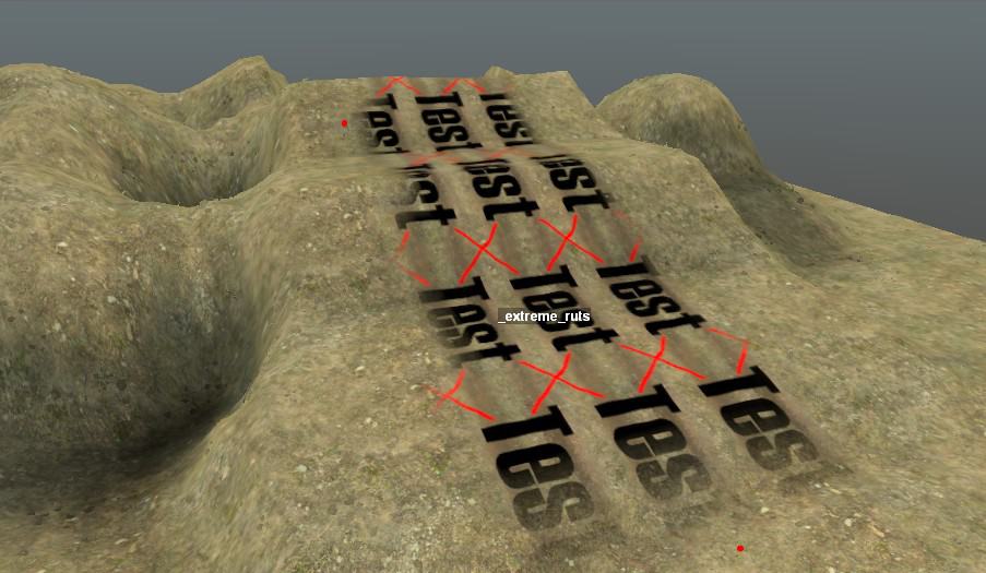
HeightmapOffset="{file}"
Specifies a texture which the editor uses to modify the height of the terrain under the road. Unlike TextureHeight, this is a real height change. The effect is applied after flattening.
Example heightmap offset textures are in Media/prebuild/common/hmoffset_*__s.tga. You can put your own files in the same directory since they are directly used only by the editor and not by the game.
The resolution of the built-in textures is 64 by 32 or 32 by 32, and the texture is stretched the same way as for the other road textures. You can use a greater resolution, but the height effect is applied with the same resolution as the underlying terrain, so not very many pixels are needed for maximum fidelity of a normal width road. The “pixelated” nature of the terrain also means that sharp ruts applied at an angle will have jagged edges.
The offset is determined by the red channel. The minimum channel value corresponds to a rut about 2 meters deep. The maximum channel value corresponds to a bump about 2 meters high. The built-in roads use much less extreme offsets, of course.
Where two roads with a height offset meet, only the offsets from the second road are applied. Offsets are applied even if the second road isn’t displayed. If the second road does not have a height offset, the offset of the first road is unaffected.
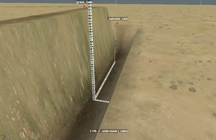
LandmarkPart="{value}"
Determines the fraction of the road width that is drawn on the navigation map. The default is 0, which results in nothing being drawn on the map. Most built-in roads set the value to 1. The number can be greater than 1 to draw a wider area or between 0 and 1 to draw only part of the road width.
If the road width is scaled differently than the default, the drawn part is also scaled accordingly.
LandmarkColor="{color}"
Specifies the color to draw on the navigation map for the road. The color is specified as described in the “Colors” section of this guide.
The built-in roads use either “(100; 100; 100)” for gray or “(100; 90; 80)” for brown. The road edge is always drawn as dark gray. If the LandmarkPart is non-zero, and the LandmarkColor is not specified, it defaults to black.
Custom Non-Road Overlay
You might notice that the built-in XML files don’t fully describe the non-road overlays. So you can’t create a new custom non-road overlay, and you can’t do much to change the existing overlays. One thing you can do is change how cliff overlays are displayed on the navigation map by changing their LandmarkPart and/or LandmarkColor prebuild properties. These properties are described in the Custom Road Overlay section above.
Custom Overlay Brush
Overlay brushes can be customized to add any repeated models to a road (or other overlay).
As with plant and grass brushes, overlay brushes are created in Media/prebuild/common/brushes.xml
<OverlaysPlants>

<{OverlayBrushName}>

<ModelType

Brands="{names}"

Interval="{value}"

{properties}

/>

...

</{OverlayBrushName}>

...

</OverlaysPlants>
Warning: An update to the MudRunner Editor may wipe out your changes to the brushes.xml file. Make sure to keep a copy! (I tried creating my own brushes.xml file in my mod directory, but it doesn’t get used.)
Multiple ModelType tags can be used to generate multiple series of models along the road (e.g. to place models on both sides of the road).
For the property descriptions below, “forward” means pointing along the spline from a low numbered point to the next higher numbered point.
Brands="{names}"
A comma-separated list of model names. The models placed by the brush are selected randomly from this list.
Interval="{value}"
Specifies the separation between models (in meters) as measured along the road centerline. The distance is approximate since a curved road will have some stretched or squashed segments.
AlignToTangent="{value}"
By default, a model is placed with its X axis pointing forward along the road. AlignToTangent rotates the model by value*90° counterclockwise.
DirOffset="{value}"
Forward offset of each model, following the curve of the spline. The first model is offset forward by value+4 meters from the start point of the road.
DirOffset can be negative, but if a model would be placed before the start point, it is placed at the start point instead. In the extreme, this can result in multiple models being placed at the start point.
DirOffset can be positive, but if a model would be placed closer than 4 meters from the end of the road, it is not placed at all. I.e. model placement rules are not symmetric.
TangentOffset="{value}"
Offset to the right from the centerline (perpendicular to the spline). Negative numbers offset to the left. The offset does not take into account the width of the road. Note that models offset to the outside of a curve are spaced further apart and models offset to the inside of a curve are closer together.
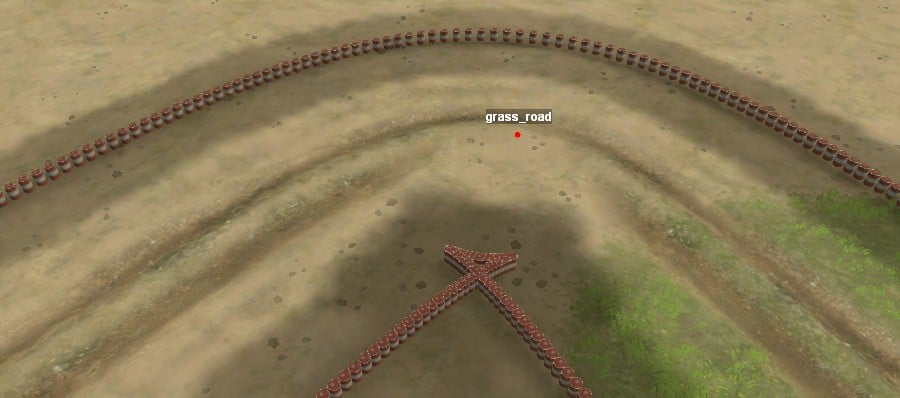
Divergence="{value}"

Perpendicularity="{value}"
No effect. And no, the use of these properties by the built-in brushes doesn’t imply that you can place plants. I tried that.
Special Models
Individual logs can be created using the overlay brush. They are physically active in the game and can be picked up and delivered to a lumber mill.
Log kiosks and log scavenge points can be created, but they aren’t functional when playing the game.
Blockposts can be created and are active in the game.
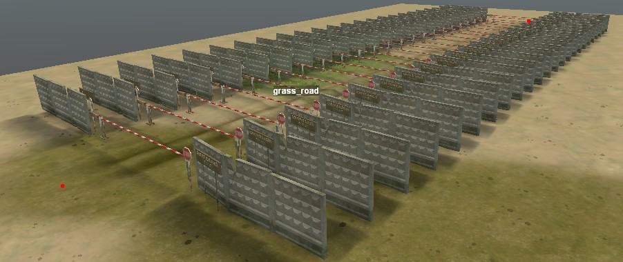
Custom Static Model
Creating your first custom model is a big hurdle. 3-D modeling tools have a steep learning curve, but that may be the easy part. For integrating models into MudRunner, there is no documentation, there are no official examples, and there are countless ways to get something slightly wrong so that your model looks fine in the 3-D modeler but doesn’t show up in the MudRunner editor at all.
It is possible to make movable, flexible, and/or breakable models. This guide only describes static models, however.
A MudRunner model requires the following files:
{mod directory}/meshes/models/{name}.x contains the 3-D model.
{mod directory}/meshes/models/{name}.xml specifies the appearance of the model (mesh XML).
{mod directory}/textures/models/ contains the textures for the model.
{mod directory}/classes/models/{name}.xml specifies the physics of the model (class XML).
I’ll describe these one at a time.
3-D Model
You’ll create the 3-D model with a 3-D modeling tool and export it in DirectX format for use in MudRunner. Blender is a free 3-D modeling tool, and it is what I use.
This guide uses the word ‘model’ to refer to either a MudRunner model or a generic 3-D model that could be used by a MudRunner model or other MudRunner object. Hopefully it’ll always be clear in context, but I apologize in advance for any confusion.
The 3-D model is organized using a hierarchy (tree) of frames. If there is more than one top-level frame, MudRunner creates a single unnamed top-level frame to encapsulate them.
The 3-D model contains multiple meshes in its hierarchy, each of which contains multiple polygons in 3-D space. The model must contain at least one mesh that represents the visible geometry of the model plus at least one mesh used for detecting collisions.
The collision detection mesh is implicitly multi sided. E.g. the mesh can be a simple planar polygon, and MudRunner will check for collisions on both sides of the polygon as well as its edges.
Each collision detection mesh must be directly contained by a frame that has a name starting with “cdt” (with any mix of lowercase and uppercase). This frame is referred to as a “cdt frame” in this guide. These frames are not made special by being in a cdt frame (Your 3-D modeling tool may also give a name to the polygon mesh itself. However, this name is not exported to DirectX. The MudRunner model viewer calls it cdt_mesh.)
The visible meshes can have any name that does not start with “cdt” (with any mix of lowercase and uppercase).
A cdt frame must contain a collision detection mesh, but it may contain additional frames. Being inside a cdt frame does not make these child frames special, and they may contain any hierarchy including additional collision detection meshes or visible meshes.
Blender Tips
Most Blender discussions on Spintires forums include awkward workarounds for limitations of the original Spintires game. These are no longer necessary for static MudRunner models. If you’ve hacked your DirectX exporter script, I recommend that you remove those hacks.
- The frame hierarchy can contain translations and rotations (but only unit scaling).
- The default DirectX exporter adds a ‘Root’ frame to convert between Blender coordinates and MudRunner coordinates.
- MudRunner allows the default cdt frame to be under this ‘Root’ frame.
In Blender, select File→Export→DirectX to export. Click to clear the checkbox for “Export Selected Objects Only” so that all meshes are exported. (The exporter automatically skips non-mesh objects like the camera and lamp.) Blender doesn’t remember this changed setting from session to session, so you’ll need to remember to clear the checkbox every time. Otherwise the editor will complain that the cdt or visible mesh is missing (depending on which one you had selected when you exported).
The default coordinate transformations are correct: MudRunner expects left-handed coordinates with the Y axis up. Your model should have standard normals pointing outward, and you should not flip them.
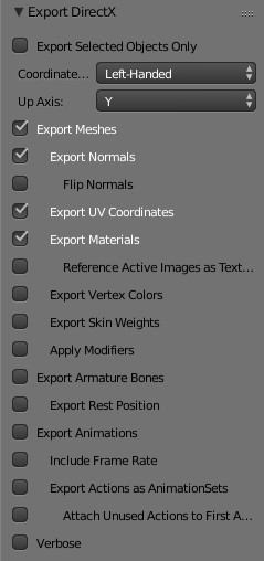
There is also a DirectX exporter for Blender that is customized to better support MudRunner. See the ‘MudRunner Exporter for Blender’ section for details.
If you’re still applying Blender hacks that you used for the original Spintires, you may have any of the following model errors in the MudRunner editor and game:
- The model is inside out. You probably have a negative scale being applied somewhere in your model. All scales should be positive.
- The model is darker on top than at the bottom. Your normals are pointing the wrong way. They should point outward in the modeler, and you should not flip them during export.
- Your model has the wrong default orientation when created in the map (e.g. the top of the model points sideways). Make sure to export with left-handed coordinates with the Y axis up.
- The game complains that the cdt is missing or the visible mesh is missing. Make sure to export all objects, not just the selected object(s).
The Blender exporter converts punctuation and spaces in names to “_”. Keep this in mind when referring to parts of the 3-D model in the XML.
The Model Viewer
The MudRunner Editor has a model viewer built in. To view your DirectX model, double click on it in the File View. The editor offers to create a mesh XML file for you in the meshes/models directory. Click “Yes”.
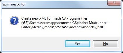
Now double-click the created XML file to view your model. Your model is displayed with a plain white texture. Adding textures or colors to your model is covered in the next section.
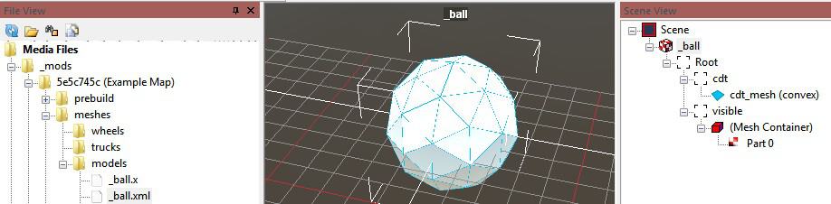
Clicking on different items in the Scene View selects and highlights different aspects of the model. The selected item may also give you controls to adjust the position, rotation, and scale of your model parts. However, there is no way to save your changes.
By default, the collision detection meshes are shown as blue wireframes. If you click on a cdt_mesh in the Scene View, it turns solid blue. While you’re looking at the cdt_mesh, note whether it is described as box, convex, or mmop. MudRunner determines the cdt mesh shape automatically. Box is the best performing, and mmop is described as “by far” the worst performing.
Click on a “(Mesh Container)” to make all other visible meshes disappear (although cdt wireframes remain). Click on a part within a Mesh Container to make it solid red.
Model Mesh XML (Material)
Examples are in MeshCache.zip/models_*. The cached mesh files contain multiple file types in one file, but with the right file viewer you can browse the XML contents at the beginning of the file (and lots of binary junk later in the file).
If you double-clicked the .x file in the previous section, the editor created a simple mesh XML file for you. But you’ll want to expand it to make your model something other than pure white. Your file goes in {mod directory}/meshes/models/{name}.xml
<CombineXMesh {properties}>

{materials}

</CombineXMesh>
The object viewer automatically notices changes to the mesh XML and offers to reload it. If you change the .x file, however, you’ll need to close the XML file and reopen it to see the change.
CombineXMesh Properties
Type="Model"
Almost every built-in model has this property, so I recommend including it as well. It is the default, however, and so not strictly necessary.
File="{name}"
Normally your DirectX model, mesh XML, and class XML must all have the same base filename. However, this property allows multiple MudRunner models to share the same DirectX model. E.g. if _ball2.xml includes File=”_ball”, it uses _ball.x as the DirectX model.
If you double click a .x file when a corresponding .xml file already exists, the MudRunner Editor offers to make a new XML file with this property for you.
Materials
When you exported your model to DirectX, your textures were not included. You can re-attach textures (or simple colors) to your model using one or more Material tags.
<CombineXMesh Type="Model"[>

<Material {Material properties} />

[...]
</CombineXMesh>
One or more Material tags can be included with your model in order to apply any number of textures/colors to different parts of it. Material properties are described below.
MeshParts="{name}"
Specifies a portion of the 3-D model for which to apply the material. The MeshParts property must specify the direct containing frame of a mesh, not a higher hierarchical level. Multiple names can be specified, separated by commas. If MeshParts isn’t specified, the material is the default material for the model.
If a mesh was modeled with multiple materials (and the material list was exported), then the mesh XML can specify a material for each part of the mesh that had a different material. These mesh parts are named in the MeshParts property as “{frame} {partnumber}”, e. g. “chassis 0”. The part number can be verified in the model viewer, described in the previous section. If the part number isn’t specified in the MeshParts property, part 0 is assumed.
DiffuseMap="models/{filename}"
The DiffuseMap is a standard texture to apply to your model, using the UV mapping that you set up in your 3-D modeler. Your texture file can have any common image file type and associated extension, e.g. “{name}.png”. As with other textures, ending the name with __d or __d_a is recommended.
Note that the path to the file assumes {mod directory}/textures. Usually you’ll put your texture in the models subdirectory as indicated above, but it can be anything, e.g. if you’d like to reuse a texture that is also used for a material.
Example textures can be found in TextureCache.zip/models_*.dds
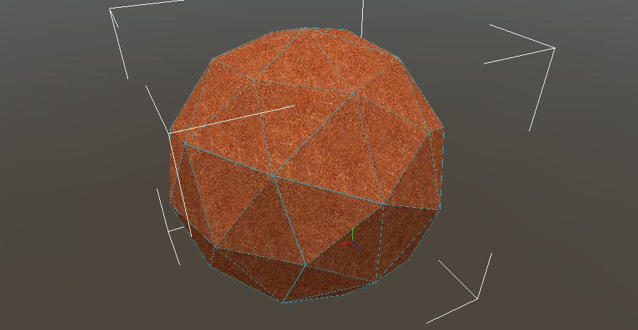
DiffuseMultiplier="{color}"
Shifts the pixel colors by the specified color. This effect can be applied on top of a texture or on top of the default white. The color is specified as described in the “Colors” section of this guide. A standard white color means “no change”. Darker, brighter, or tinted colors modify the DiffuseMap texture or the default white as per the color.
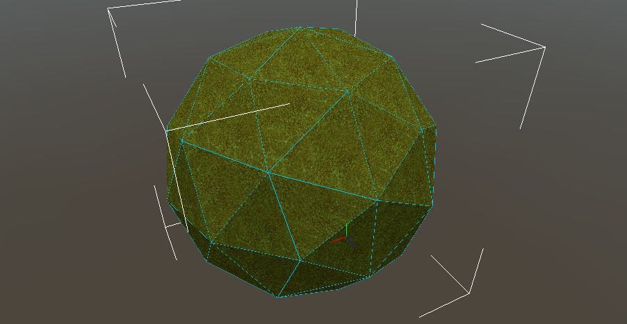
AlphaKill="true"
Makes the mesh transparent where the texture is transparent. By default the texture’s alpha channel is ignored. When AlphaKill is used, every pixel in the alpha channel must be fully opaque or fully transparent. If any pixels are partially transparent, MudRunner will refuse to read the texture.
Note that by default, the inside of the model is already transparent. So any holes on the front surface allow you to see all the way through.
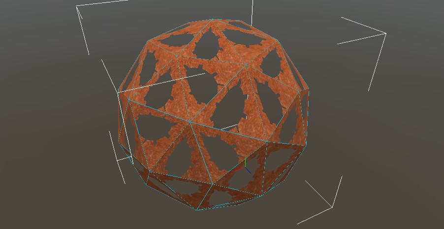
TwoSided="true"
Makes the mesh visible from both sides. Useful for thin parts of the model that are the same on both sides. Note that this may incur a performance penalty, so use it only where it’s truly needed.
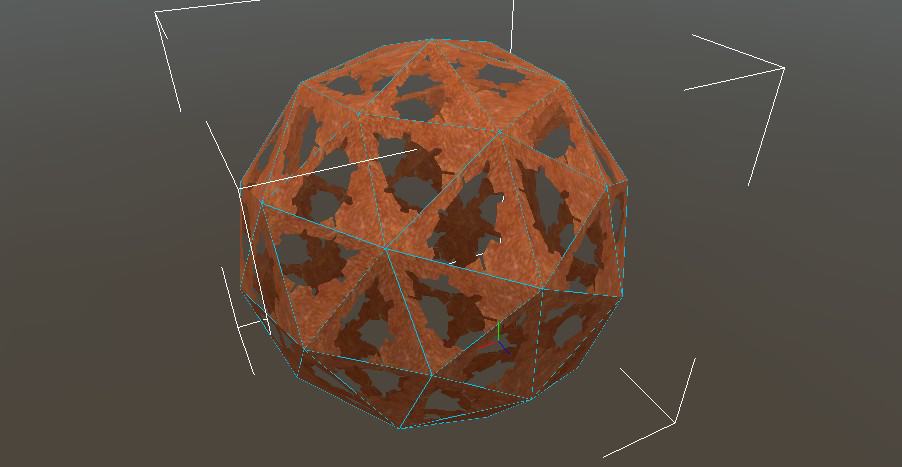
BacksideLighting="{value}"
Specifies the amount of light on the side of the object opposite the sun (i.e. polygons facing away fromt the sun). 0 is maximum shadow. 1 is no shadow. The default is 0.2.
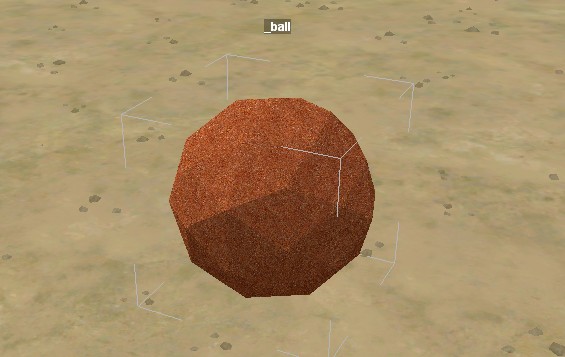
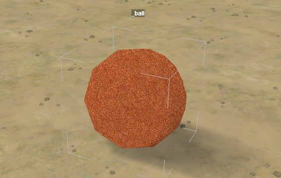
NormalMap="models/{filename}"
Add a normal map to the model.
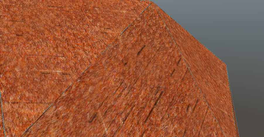
BTW, a specularmap is not supported by models.
DetailMap="models/{filename}"
Tiles a grayscale texture across the model to add detail. By default, the DetailMap texture uses the model’s UV coordinates multiplied by 8. E.g. if a model’s polygon stretches entirely across its DiffuseMap texture, then 8 copies of the DetailMap are tiled across the same distance. However, the DetailMap doesn’t scale with the model. E.g. for the same example model at scale 0.25, only 2 copies of the DetailMap are tiled across the polygon.
The DetailMap is combined with the other colors of the model by this formula:
final_color = orig_color * DetailMap_brightness * 2
DetailMap is used by the rock models. The recommended filename suffix is __s_d.
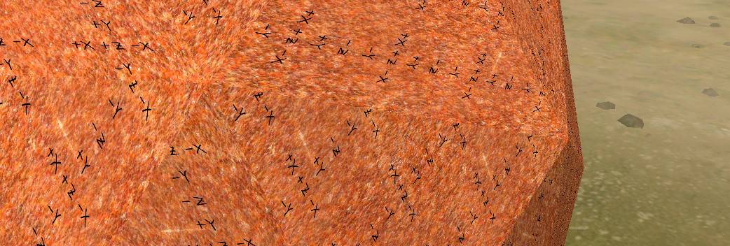
Model Mesh XML (cont’d.)
Continuing with more properties of the Material tag…
Light Rays
Blending="additive"

IsSfx="true"
These Material properties are always used together and aren’t noticeably useful when used separately. They change the named mesh part from being normally opaque to being a transparent light ray that adds color to everything seen through it.
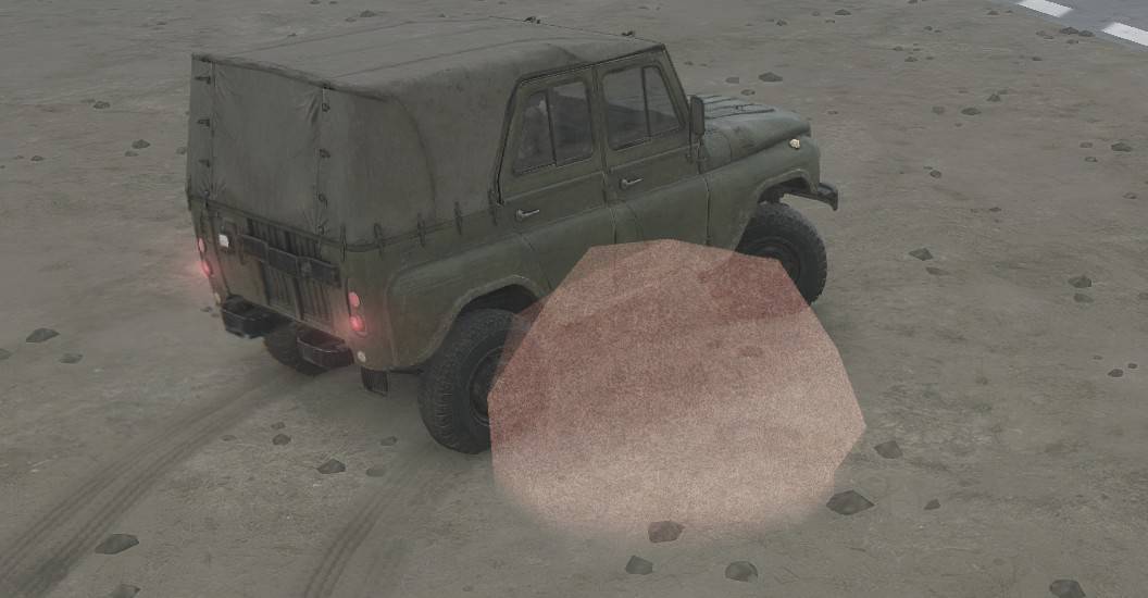
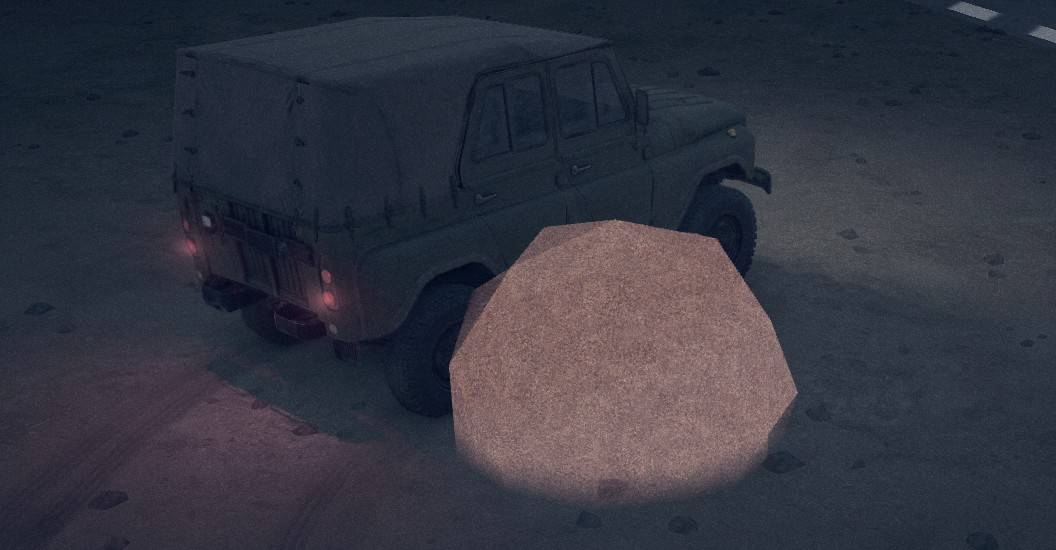
The built-in streetlight use this material to cast barely visible light rays. The light model includes a couple of rectangles hanging below the light in an X pattern. A grayscale texture give the light rays their shape, and a very dim color is applied to reduce their glow to almost unnoticeable.
<Material

MeshParts="plant 4"

Blending="additive"

DiffuseMap="sfx/light_ray__s_d.tga"

DiffuseMultiplier="g(213; 208; 235) x 0.06"

IsSfx="true"

TwoSided="true"

/>
BTW, the sfx/light_ray__s_d.tga DiffuseMap used by the built-in models provides a nice generic shape to the light cone that is likely to also be useful for custom models.
A material with these properties isn’t drawn at all in the MudRunner Editor. It is only visible in the game. However, you can see the ghost polygons for the light rays when you select the model in the editor.
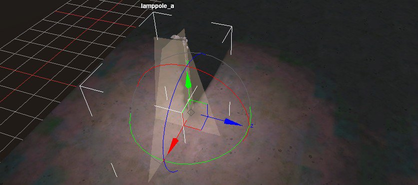
ModelMaterial
The ModelMaterial tag with its own optional properties can be added within the Material tag.
<Material {material properties} >

<ModelMaterial {modelmaterial properties} />

</Material>
ModelMaterial Properties
IsWheelTracks="true"
Allows tracks to be laid on the model material by muddy tires only. A clean tire never leaves tracks on a model. IsWheelTracks is used by bridges, individual logs, and rocks.
Clean tires never leave tracks on a model. There is no equivalent to the WheelTracks property used by material and road overlays.
NoOcclusion="true"
Prevents occlusion on the material by another model or plant (the Occlusion tag of the other object, as described in the Model Shadows section). Note that this property has no effect on cast shadows.
NoOcclusion is used by bridges and individual logs. Why these models should be immune from occlusion, I don’t know.
Model Class XML (Physics)
Examples in Media/class/models/*.xml
Your file goes in {mod directory}/class/models/{name}.xml
<ModelBrand {ModelBrand properties} >

<PhysicsModel>

<Body {Body properties} />

<Flare Color="{color}" Size="{value}" {Flare properties} />

...

</PhysicsModel>

<Occlusion {Occlusion properties} />

<StaticLights>

<StaticLight Color="{color}" AttenEnd="{value}" {StaticLight properties} />

...

</StaticLights>

</ModelBrand>
There are many additional tags and properties for movable, flexible, and/or breakable models. For now, however, this section only describes static models.
You can add your model to a map once you have created your DirectX model, mesh XML, and class XML. You may need to Rebuild Terrain or reopen your map to pick up changes to these files.
ModelBrand Properties
ClipCamera="false"
The camera is allowed to pass smoothly through the model (rather than being forced to pass around it or warp to the other side). Works best for semi-transparent models such as slat fences or thin models such as poles.
ApplyNormalInReference="false"
When the model is imported as part of a reference map and does not end up on flat terrain, the model is not tilted to match. Used for some poles.
NoLandmark="true"
Does not create a mark on the navigation map. Used for some poles.
By default, models are shown on the map with a grey smudge. However, the editor only samples a few XZ points per terrain block (roughly every 3 meters). Small objects might not be marked at all. Large objects may get multiple smudges.
The bitmap used for the landmark is in Media/prebuild/common/landmark_model.tga
NightLightingShadowsAllowCap="true"
Unknown purpose. Used for breakable models plus a seemingly random collection of buildings and rocks.
DynamicModel="true"
Used only for dynamic models, of course. See the Custom Dynamic Model section for details.
Body Properties
ModelFrame="{name}"
Specifies a frame that directly contains a cdt frame. The default is the empty string, which causes MudRunner to select the top-level frame. Recall that if the .x file contains multiple top-level frames, MudRunner automatically creates a single top-level frame to contain them.
Common practice for a static model is to make the cdt frame a direct child of the top-level frame. If this is done, the ModelFrame property does not need to be specified for the body tag. Note that the cdt frame must be the child of another frame. If the top-level frame is the cdt frame, there is no way to get MudRunner to recognize it as such.
The XML can contain multipletags, but only the first one is used for a static model. If multiple separate collision-detection boxes are needed, they must be created as a single mesh with disjoint polygons.
Collisions="{type}"
The type is usually “Dynamic”, which implies a normal object that can be collided with. A few built-in models are missing a Collisions property, but the behavior seems to default to “Dynamic”.
The other option for a static model is “None”, in which case collisions are ignored. The model must have a cdt frame even if Collisions=”None”.
Friction="{value}"
The coefficient of friction. Friction is applied when a truck drives over or rubs against the model.
The default friction is ~1.0, which is roughly the same as smooth terrain. The friction cannot be less than 0.
IsStaticSoil="true"
A truck driving across the model throws dirt clods from its tires. This is similar to IsExtrudable=”true” for material, although the model does not deform.
NoSoftContacts="true"

NoSoftImpulse="true"

IsGameAsphalt="true"
I have spent a lot of time experimenting, but I still have no idea what these do.
NoSoftContacts is used for bridges, individual logs, fences and other small breakable objects, but not breakable signs. NoSoftImpulse is used for bridges. IsGameAsphalt is used for bridges with an asphalt roadbed.
Model Flares and Lights
The flare tag is optional, and any number of flare tags may be included. Each tag creates a glowing ball of light, but that light does not actually illuminate its surroundings.
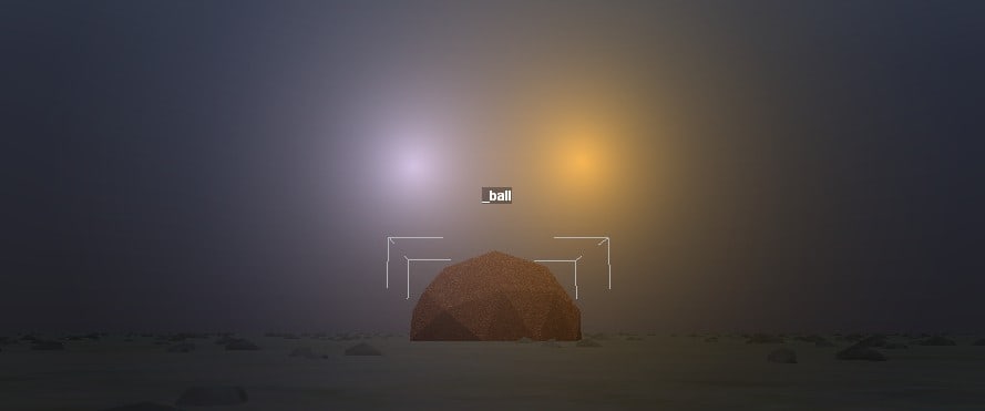
In the game, flares also illuminate dust on the virtual camera lens.
Reiterating the contents of class/models/{name}.xml:
<ModelBrand {ModelBrand properties} >

<PhysicsModel>

<Body {Body properties} />

<Flare Color="{color}" Size="{value}" {Flare properties} />

...

</PhysicsModel>

<Occlusion {Occlusion properties} />

<StaticLights>

<StaticLight Color="{color}" AttenEnd="{value}" {StaticLight properties} />

...

</StaticLights>

</ModelBrand>
Flare Properties
Color="{color}"
The color of the flare. Also specifies the brightness of the center of the flare when viewed at the optimal angle at night. The color is specified as described in the “Colors” section of this guide.
The maximum brightness appears to be (511,511,511). Required.
Size="{value}"
The apparent diameter of the visible glow in meters when viewed at the optimal angle at night. The glow falls off rapidly from the center, so the exact boundary is nebulous. A flare shining through a model’s volume (e.g. a flare placed inside its own model) falls off about 10x more rapidly within the volume than it does when not occluded. The flare size does not scale with the size of the model. Required.
SizeMultAtDay="{value}"
The relative size of the flare’s glow during the day. This factor is multiplied by the Size value to get the size during the day. The default value is 1.
This property works correctly in the game, but not the editor. The editor always uses the property, even when changed to night mode.
The built-in flares in the models.xml template file specify a SizeAtDay property, but this is incorrect and does not work.
ColorMultAtDay="{value}"
The change in brightness during the day. The built-in flare sources use a value of about 0.5. The default is 1.
Pos="({X}; {Y}; {Z})"
The position of the flare relative to the base of the model. The default position is directly at the base: (0; 0; 0). Scales with the size of the model so that it stays in the same relative position.
Dir="({X}; {Y}; {Z})"
The orientation of the flare. The flare is brightest when looking at the flare from that direction. The default direction is straight up: (0; 1; 0).
DirAngle="{value}"
The flare brightness falls off at angle from Dir (above) until it reaches 0 at the angle (in degrees) given by DirAngle. A typical built-in value is 120. The default is “0”, which is a special value that results in an omnidirectional flare with no fall off in any direction.
If the DirAngle is non-zero, there is a bug when the model’s scale is greater than 1. In that case, the flare’s maximum brightness is at an angle from Dir of DirAngle * (1 – 1/Scale)). The flare abruptly cuts off at any angle close to Dir than that. Conversely, if the model’s scale is less than 1, the flare is attenuated from its maximum brightness, even when looking from Dir.
AttenStart="{value}"

AttenEnd="{value}"
The size of the visible glow changes with distance (in the same way as any other object), but its brightness initially does not. Attenuation of the brightness begins at the distance (in meters) given by AttenStart, and the brightness falls to zero at the distance given by AttenEnd. These values do not scale with the size of the model. The default values are about 40 and 120.
Reflections=”true”
Used only in trucks. No effect for models.
StaticLight Properties
A static light is not itself visible, but it brightens anything that it shines on. A static light is best paired with a flare: the flare provides the visible source of illumination, and the light provides the actual illumination.
Warning: Unlike most other information in the class XML file, the editor doesn’t reload static lights when you Rebuild Terrain. You must reload the map, then Rebuild Terrain.
Static light properties primarily influence how the ground is lit. When lighting an object, MudRunner measures the brightness of the light at ground level, then lights the object with that brightness, from the direction of the light source. E.g. a light pointing at the ground will still light objects floating above the light, and a light pointing straight up will not light objects directly above it.
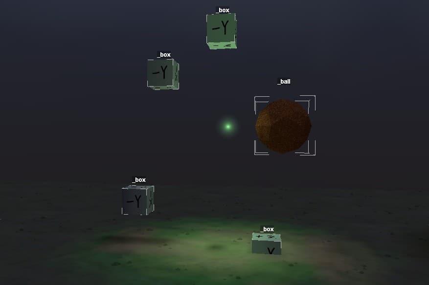
Color="{color}"
The color of the light. Also specifies the brightness of the light. The color is specified as described in the “Colors” section of this guide. Required.
AttenEnd="{value}"
The maximum distance at which illumination is cast, in meters. The illumination falls off rapidly at the end of the range. Required.
An AttenEnd value of 32 or greater results in an infinite number of errors, so the editor effectively hangs.
AttenEnd scales with the size of the model, and the scaled value is allowed to exceed 32.
However, if the scaled value is greater than ~56.3 meters, a different error dialog is generated (but the editor doesn’t hang). In addition, some effect causes the amount of illumination to decrease with scale until it disappears entirely.
There is no AttenStart property for static lights.
Pos="({X}; {Y}; {Z})"
The position of the light relative to the base of the model. The default position is directly at the base: (0; 0; 0). Scales with the size of the model so that it stays in the same relative position.
Dir="({X}; {Y}; {Z})"
The orientation of the light. The light shines brightest in that direction. The default direction is straight up: (0; 1; 0), which isn’t very useful.
CreateSuperLight="true"
No apparent effect.
OuterCone="{value}"
The maximum angle (in degrees) from its primary direction at which the light provides illumination. The default is 180°.
InnerCone="{value}"
The angle (in degrees) from its primary direction at which the light begins to attenuate. I.e. it is full brightness from 0° to the InnerCone angle, and then it falls off from the InnerCone angle to the OuterCone angle.
All of the built-in static lights set InnerCone=”0″. The default is 180°.
If InnerCone=OuterCone, the light is full brightness all the way to its outer angle. If InnerCone>OuterCone, the specified values are ignored and use their default values instead.
ExpAtten="true"
The light falls off more gradually at the edges of the light cone and at distances approaching AttenEnd. By default, the light stays brighter longer, then falls off more rapidly at the limits.
Shadows="true"
The light casts shadows. As a performance optimization, an object does not get a shadow from each light source. Instead, each object (including the player’s truck) casts shadows based on the average of the lights illuminating it (for those lights that do cast shadows).
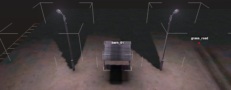
Model Shadows
Reiterating the contents of class/models/{name}.xml:
<ModelBrand {ModelBrand properties} >

<PhysicsModel>

<Body {Body properties} />

<Flare Color="{color}" Size="{value}" {Flare properties} />

...

</PhysicsModel>

<Occlusion {Occlusion properties} />

<StaticLights>

<StaticLight Color="{color}" AttenEnd="{value}" {StaticLight properties} />

...

</StaticLights>

</ModelBrand>
Cast Shadows
There are no properties on a model that affect that shadow it casts.
When you Rebuild Terrain, the MudRunner Editor automatically generates both day and night shadows from the visible model geometry. Shadows are cast during the day from a virtual sun at a roughly 45° angle between the −X and +Y axes (high in the west). Shadows are cast during the night from StaticLight sources, described in the previous section. These shadows are cast not only on the ground, but on both static and dynamic objects such as the player’s truck.
Dynamic lights (i.e. ones on a truck) do not cast shadows.
Occlusion
In addition to the cast shadows described above, models can have an associated occlusion texture that darkens the ground around the model. My best guess is that the occlusion represents the shadow from the ambient sky (e.g. the blue sky excluding the sun), although the occlusion is also visible at night.
The occlusion shadow is applied around the model’s XZ coordinates, regardless of how high above ground or even how low below ground the model is placed. This is unfortunate because it makes partially buried models look rather goofy.
Warning: Unlike most other information in the class XML file, the editor doesn’t reload occlusion properties when you Rebuild Terrain. You must reload the map, then Rebuild Terrain.
Texture="{filename}"
Examples in Media/prebuild/common/occlusion_*.tga
Your file goes in {mod directory}/prebuild/common/{filename}
The occlusion texture file is a greyscale bitmap in which the brightest pixels represent the darkest occlusion shadow.
The occlusion texture is used only during prebuild, so it isn’t cached in the texture cache, and it doesn’t require the usual texture filename conventions. The built-in occlusion texture filenames all start with occlusion_*, which seems like a good convention.
If the Texture is left unspecified, the MudRunner Editor uses occlusion_radial.tga, a fuzzy circular blob.
Size="({Z}; {X})"
Specifies the dimensions that the occlusion texture is stretched to in the model’s Z and X dimensions. Defaults to “(0; 0)”.
There is no particular maximum occlusion size, but the occlusion is only drawn in the terrain blocks that include visible parts of the model and their neighboring terrain blocks.
Intensity="{value}"
Specifies the intensity of the occlusion shadow, between 0 and 1. The default is 1.
The occlusion shadow’s intensity also increases proportional to occlusion size.
Model GameData (for logs)
The built-in logs include an additional GameData tag within ModelBrand. E.g.
<GameData LoadAddons="load_logs_medium" LoadType="MediumLogs">

<LoadPoint Pos="(-2.0;0;0)" />

<LoadPoint Pos="(2.0;0;0)" />

</GameData>
When a packed load of medium logs is unloaded (e.g. by the truck menu item or by tipping the truck over), the packed load is removed and individual logs are created in its place. This GameData tag says that the model is a candidate model for substitution during this process.
I recommend that you don’t attempt to use this tag because doing so could affect unrelated maps. Normally, any custom objects that you create are not included in other maps and so cannot influence them. However, this GameData tag creates a reverse association such that a load of logs could potentially turn into your model when it is unloaded! Once someone has downloaded your mod, this substitution could occur on any map, which would make it very confusing and frustrating for people to debug if they don’t want it to happen.
It may be possible to create an entirely new LoadType along with associated custom addons and models. In that way, it would not substitute for the standard packed log loads. However, that would require truck customization (if it works at all), and that is outside my scope.
Custom Dynamic Model
These sections build upon the concepts introduced for static models.
A model can be created with a hierarchy of body tags, where each body has an associated cdt frame. The bodies (and thus the cdt frames) are connected by constraints. External and internal forces can move and rotate the cdt frames, which cause corresponding movement of the entire associated bodies.
This body hierarchy may replicate the 3-D model hierarchy, but it doesn’t have to. There must be only one top-level body tag. This body can contain any number of child bodies, each of which may contain child bodies, etc. Any additional top-level body tags are ignored.
Each child body must be attached to its parent with a physical constraint such as a hinge. Additional constraints can also be placed between bodies in different parts of the body hierarchy.
Each constraint can have a motor in it which resists motion of the constraint and attempts to return the constraint to its initial position.
Any cdt frame that is not directly under a body frame is ignored and has no effect.
Any visible mesh that is not contained by a body is implicitly a static portion of the model that does not participate in physics. The same applies to static lights created in the XML. Additionally, occlusion and shadows are static, so they may look unnatural when an object moves. However, flares are attached to the top-level body and will move and rotate as the top-level body moves and rotates.
Example class XML file showing the body hierarchy:
<PhysicsModel>

<Body

ModelFrame="base"

Collisions="Dynamic"

>

<Body

ModelFrame="hinge"

Collisions="Dynamic"

Mass="200"

>

<Constraint

Type="Hinge"

AxisLocal="(0;0;1)"

MinLimit="-360"

MaxLimit="360"

>

<Motor Damping="500" Spring="5000" Type="Spring" />

</Constraint>

</Body>

</Body>

</PhysicsModel>
Physics Distance Limits
As a performance optimization, MudRunner does not calculate physics for a body if that body’s cdt mesh is too far from the player’s truck. When the player’s truck approaches within ~1 meter, physics is enabled for the body. When the player’s truck gets further away than ~10 meters, physics is disabled for the body. Ideally, you want any model motion to be damped before the player’s truck gets too far away so that it doesn’t suddenly freeze mid-motion.
MudRunner may also halt a model’s motion if its various velocities and forces get too low, even if it is in an obvious non-equilibrium state. E.g. a pendulum may stop swinging when at the top of a short arc, where it is nearly stopped and the force on it is low.
Activating one body of a model also activates any other body of that model within about 10 meters. Be careful with long range constraints! If a constraint is applied to a distant body that isn’t checking normal physics rules, weird things may happen.
Finally, if a body’s cdt mesh moves more than ~10-30 meters from its original position, it may stop responding to the truck. The body may also flicker or disappear. You can avoid this by adding the property DynamicModel=”true” to the ModelBrand tag. E.g.
<ModelBrand NoLandmark="true" DynamicModel="true">
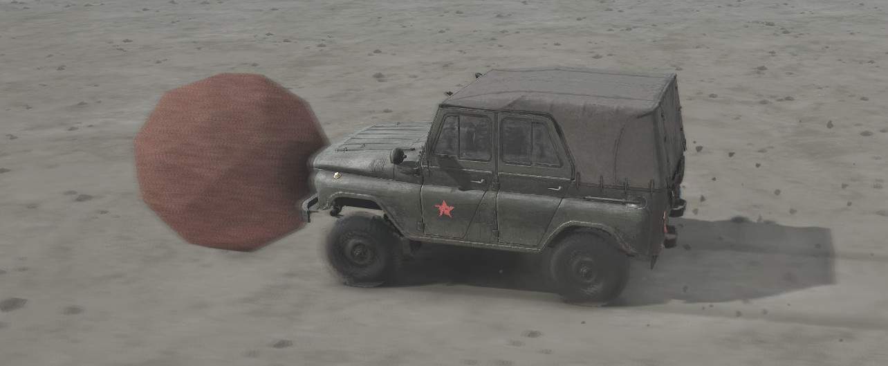
Dynamic Model Body
Body Origin
Each body in the model defines its own coordinate system for use by body and constraint properties. This coordinate system is located and rotated as it is in the 3-D model. The location and rotation of this coordinate system can be viewed in the MudRunner Editor’s model viewer by selecting the body’s model frame. (If you use my Blender exporter and recommended settings, remember that the Y axis is inverted from its Blender orientation.)
In the image below, notice that the frame’s coordinate axes (in the center of the cube) do not match the global axes (in the lower left corner of the image).
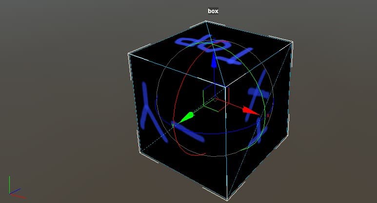
Unused Body
If a body has no associated visual mesh, then the body cannot participate in physics regardless of its body properties or constraints on other bodies. The map editor will display an error for this case.
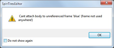
The model viewer doesn’t display an error for unused bodies, but they can be recognized in the model viewer because they don’t show a rotation/translation interface. In the below images, the “blue” body has an associated CDT frame, but no associated visual mesh.
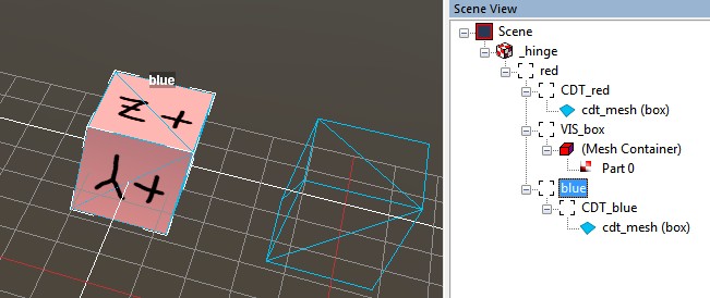
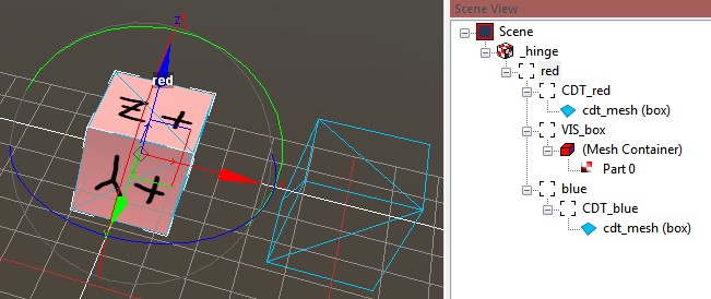
Body Properties
The body tag was already introduced for static models. I’ll reiterate those properties already introduced, but with an emphasis on how they work for dynamic models. Below I also list additional properties that apply only to dynamic models.
ModelFrame="{name}"
Specifies a frame that directly contains a cdt frame. The default is the empty string, which causes MudRunner to select the top-level frame.
The body includes the named model frame and all of its child frames, but excluding any hierarchy that is named by another body tag. Everything in the body moves as a unit, affected by the constraint physics and any collisions with the cdt mesh.
Collisions="{type}"
“Dynamic” (the default) or “None”. The body must have a cdt frame even if Collisions=”None”, but this cdt frame is then ignored.
If Collisions=”Dynamic”, MudRunner checks for collisions with trucks and with other models. It does not check for collisions with other bodies in the same model. It also doesn’t check for collisions with plants. Water also has no effect on models (no buoyancy or drag). A body will sink somewhat into mud, but not to the full mud depth. It may therefore appear to float over deep, wide ruts.
Friction="{value}"
The coefficient of friction.
The default friction is ~1.0, which is roughly the same as smooth terrain. The friction cannot be less than 0.
When two models rub against each other, their coefficients of friction are multiplied together.
IsStaticSoil="true"
A truck driving across the body throws dirt clods from its tires.
NoSoftContacts="true"

NoSoftImpulse="true"

IsGameAsphalt="true"
Unknown purpose.
Mass="{value}"
The mass value is specified in kilograms. The higher the mass, the more force is required to move it. The mass cannot be less than 0.
A body with the default Mass=”0″ is a static body. It never moves at all, and the remainder of the properties described below have no effect.
CenterOfMassOffset="({X}; {Y}; {Z})"
A body’s default center of mass is the center of its cdt frame’s bounding box. CenterOfMassOffset shifts the body’s center of mass as specified from the default position. The displacement is in the body’s local coordinate system, but is relative to the default center of mass, not the body origin.
GravityFactor="{value}"
Specifies a multiplication factor when applying earth gravity (g=9.8m/s²) to the body. The default value is 1. The minimum value is 0 (which disables gravity on the body). There is no set maximum.
LinearDamping="{value}"
Specifies a constant resistance to motion of the body, even in the absence of friction. The default and minimum is 0.
A value of 1 creates a small drag on the body that is only noticeable over a large distance (~10 meters, depending on the model). A value of 30 is high enough that gravity can pull the body only very slowly. The value has no set limit, but values over ~100 have no additional effect.
AngularDamping="{value}"
Specifies a constant resistance to rotation of the body, even in the absence of friction. The default and minimum is 0. The value has no set limit, but values over ~100 have no additional effect.
Model Constraint Intro
Parent-Child Constraints
Every child body is connected to its parent body by a constraint. This guide generally describes the constraint as if the parent body is fixed in place while the child body moves around it, but the constraints are actually bi-directional. If both bodies are mobile, the MudRunner physics engine moves both bodies as necessary to solve the constraint, taking into account their respective inertias, etc.
A parent-child constraint is created by placing the Constraint tag within the Body tag of the child body. Only one such Constraint tag can be created within the body. E.g.
<Body {parent properties}>

<Body {child properties}>

<Constraint {constraint properties} />

</Body>

</Body>
The top-level body is the only body that is not required to have a constraint. If it is given a constraint, the implied parent is the world (which is static, of course). The built-in sign_bridge_01 is an example with this type of constraint.
Cross Constraints
Additional constraints can also be created between any two bodies of a model. A cross constraint is created by placing the constraint tag within the PhysicsModel tag, not within a Body tag. This constraint must include ModelFrameParent and ModelFrameChild properties to designate parent and child bodies for the constraint.
<Constraint ModelFrameParent="{name}" ModelFrameChild="{name}" ... />
You cannot create cross constraints relative to the world. However, you can create constraints relative to a static body in the model, which accomplishes the same thing. That static body can be set up with Collisions=”None” and no visible mesh in order to act as an invisible anchor point.
All Constraints are Flexible (Flex Springs)
All constraints have a bit of flex when pushed against the constraint. This flex allows the constraint to move slightly in any combination of the three dimensions and to also rotate around the three axes, for a total of six degrees of freedom. This feature is likely there to prevent the physics engine from exploding when a constraint is slightly violated. It has the additional feature that it reduces or eliminates impact damage when a truck knocks against the constrained body.
The flex is most noticeable when pushing the constraint in a direction for which it doesn’t have freedom of movement, or when the constraint has reached its free movement limit.
The constraint flex is resisted by virtual springs. The spring forces are tuned to the mass of the lighter body to avoid resisting flex with excessive acceleration. However, this means that a heavy truck can easily overwhelm the flex resistance of a lightweight body and push it where the constraint isn’t supposed to go. Therefore, any body that can be directly impacted by a truck should probably have a mass of at least 10 kg (or more).
Break-off Threshold
Any constraint can be given a break-off threshold. When the force imparted by the flex springs (above) exceeds the threshold, the constraint is released, allowing the body to have free movement (subject to any unbroken constraints).
<Constraint Type="{name}" {properties} BreakOffThreshold="{value}" />
Example: Media/classes/models/sign_triangle_yield.xml
If any constraint is broken in a model, the model itself is considered broken. This is true even if additional constraints hold the model together in one piece and/or attached to a static body. A broken model disappears when it is out of view of the virtual camera. A broken model also disappears abruptly while still in view if the broken part exceeds the physics distance limits discussed in the “Custom Dynamic Model” section above.
If the broken constraint is a world constraint on the top-level body, the broken model can be pushed around in the environment. However, it is still subject to the physics distance limits, so it is best to set DynamicModel=”true” in the ModelBrand tag. With this property, the broken model won’t disappear until it is out of view of the virtual camera.
Basic Constraint Types
There are four types of constraints available for models:
- Fixed
- Hinge
- Prismatic
- Ragdoll
Each constraint type is described below.
All constraint types support the BreakOffThreshold property, discussed in the previous section.
Fixed Constraint
A fixed constraint holds the child body in place relative to the parent body. E.g. if the parent body rotates, the child body rotates around it.
<Constraint Type="Fixed" />
Example: Media/classes/models/us_mailbox.xml
Hinge Constraint
<Constraint Type="Hinge" {hinge properties} />
A hinge constraint restricts the child body to rotate in a plane around a pivot axis. I.e. the child’s origin acts as the hinge joint. You can watch a short video showing this type of constraint (with thanks to the folks behind the NifTools wiki.
Example: Media/classes/models/wooden_fence_a.xml
PivotOffset="({X}; {Y}; {Z})"
PivotOffset specifies a displacement of the pivot axis from the child body’s origin. The default is (0; 0; 0), through the child’s origin. ***WARNING***: PivotOffset specifies a displacement in the global coordinate space, not the child body’s coordinate space. This is the only constraint property that behaves this way. It is presumably a bug that was never caught because no built-in assets use this property. Because the PivotOffset is in global coordinate space, rotating the model causes the pivot to change location relative to the model. I recommend that you don’t use it until the bug is fixed. Instead, make sure that the child body’s origin is exactly where you want the hinge to be.
AxisLocal="({X}; {Y}; {Z})"
AxisLocal defines the axis of the hinge joint that the constraint rotates around, defined in the coordinate space of the child body. The length of this vector doesn’t matter. Its default value is (0; 1; 0), but I recommend that you always set it explicitly.
As a special case, AxisLocal=(0; 0; 0) allows the child to rotate freely around the pivot point using any or all of the rotatation axes. In this case, MinLimit and MaxLimit are ignored since there is no axis to measure the limits against. Warning: MudRunner’s built-in assets never use this special case, so changes to the software could change its behavior.
MinLimit="{value}"

MaxLimit="{value}"
MinLimit and MaxLimit specify the minimum and maximum angles (in degrees) through which the hinge is allowed to rotate. When looking in the direction of AxisLocal, positive angles are counterclockwise. The initial angle between the two bodies is considered to be 0°. This initial 0° angle should be between MinLimit and MaxLimit; otherwise the hinge will be subject to a mighty kick as soon as the player’s truck approaches.
The default and minimum value for MinLimit is -360. The default and maximum value for MaxLimit is 360.
Prismatic Constraint
<Constraint Type="Prismatic" MinLimit="{value}" MaxLimit="{value}" {prismatic properties} />
A prismatic constraint restricts the child body to slide along one vector without rotation. You can watch a short video showing this type of constraint.
Example: Media/classes/trucks/zil_utility.xml
AxisLocal="({X}; {Y}; {Z})"
AxisLocal defines the vector of sliding movement. The length of this vector doesn’t matter.
The default value is (0; 0; 0), which is a special case that does not constraint the body at all; it can freely move or rotate in any direction. In this case, MinLimit and MaxLimit are ignored since there is no axis to measure the limits against. Warning: if the body gets too far from its original location it may flicker or disappear, even if is used. Warning 2: MudRunner’s built-in assets never use this special case, so changes to the software could change its behavior.
MinLimit="{value}"

MaxLimit="{value}"
MinLimit and MaxLimit specify the minimum and maximum distance which the constraint can slide. Positive values are in the direction of AxisLocal; negative values are in the opposite direction. The initial position between the two bodies is considered to be 0. This initial 0 value should be between MinLimit and MaxLimit; otherwise the constraint will be subject to a mighty kick as soon as the player’s truck approaches.
There are no known limits to these values.
Unlike all other constraint properties, the map editor requires that MinLimit and MaxLimit are both specified.
Ragdoll Constraint
The Ragdoll constraint will be described after this digression to talk about constraint motors.
Motor for Hinge/Prismatic Constraint
A “motor” resists motion of its constraint and attempts to return the constraint to its initial position. Each constraint can have only one motor, which is declared as a child tag of the constraint. E.g.
<Constraint

Type="Hinge"

AxisLocal="(0;0;1)"

>

<Motor Type="Spring" Spring="5000" Damping="500" />

</Constraint>
A standard Motor tag can be applied to a Hinge or Prismatic constraint. There are different motor tag variations for the Ragdoll constraint.
There are two types of Motor:
- Spring
- Position
Each motor type is described below.
Spring Motor
<Motor Type="Spring" Spring="{value}" Damping="{value}" />
The force applied by a spring motor increases with distance.
Spring="{value}"
Specifies the spring constant (k) of the motor in kg/s² (kg*s^-2). The force applied to the constraint toward its initial position is k*x, where x is its distance away from its initial position. For a Prismatic constraint, this distance is straightforward. For a Hinge constraint, the distance measures how far the body’s center of mass has traveled around the circumference of the circle.
Here are some rules of thumb for setting the spring constant for a dynamic body attached to a static body:
If gravity is pulling the dynamic body, the spring will balance the force of gravity after a displacement of 1 meter if k = 9.8 times the mass of the dynamic body.
Similarly, if a truck is pushing against the constraint, and the truck’s tires have the default coefficient of friction = 1.0, then again the spring will balance the truck’s force after a displacement of 1 meter if k = 9.8 times the mass of the dynamic body.
Damping="{value}"
Specifies the damping constant (b) of the motor in kg*m/s² (kg*m*s^-2). A damping force is applied to the constraint’s motion of b*v, where b is the velocity of the constraint’s motion.
The “critical value” is of interest because in the absence of other forces, it damps the motor’s spring as quickly as possible. The critical value is b = sqrt(4*k*m), where k is the spring constant (above) and m is the mass of the dynamic body.
Position Motor
<Motor Type="Position" Force="{value}" {optional properties} />
The force applied by a position motor is constant regardless of distance.
Force="{value}"
Specifies the force of the motor in newtons (kg*m*s^-2).
Damping="{value}"
Specifies a damping factor for the motor. The default and maximum is 1.0, which reverses the motor’s force at (nearly) the instant required to bring the constraint to a halt at its initial position. The minimum value is 0.0, which allows the constraint to vibrate slightly before settling back to its initial position. None of the built-in assets use the Damping property for position motors, so this property may be subject to change.
Tau
<Motor Type="{name}" {properties} Tau="{value}" />
The Tau property can be used with any motor type. Tau specifies the relative stiffness of the motor constraint solver, between 0.0 and 1.0.
The Havok physics engine uses an iterative approach to solve constraints. With a Tau of 1.0, Havok attempts to solve the constraint entirely in each iteration. In a complex model with multiple motors generating competing forces, a high Tau like this could cause the constraint solver to overshoot. The result is an unstable system. With a low Tau value, the system is more stable, but constraints may not be entirely solved by the end of the iterative process. With a Tau value of 0.0, the motor is effectively disabled.
I have not created complex enough models to discover the default Tau value or the effective range of useful values.
Examples are in Media/classes/trucks/*.xml
Ragdoll Constraint
<Constraint Type="Ragdoll" {ragdoll properties} />
A ragdoll constraint restricts the child body to rotate and twist around a pivot attached to the parent body, similar to a ball joint or a punching bag. You can watch a short video showing this type of constraint. You can also refer to this diagram (again with thanks to the folks behind the NifTools wiki).
Example: Media/classes/trucks/zaz968m.xml
PivotOffset="({X}; {Y}; {Z})"
PivotOffset specifies the location of the pivot point in the child body’s coordinate space. The default is (0; 0; 0), the child’s origin.
Unlike the PivotOffset property for Hinge constraints, the PivotOffset property for Ragdoll constraints correctly uses the local coordinate space.
TwistAxisLocal="({X}; {Y}; {Z})"
TwistAxisLocal defines the axis of the ball joint, i.e. the center of a cone that the constraint can swing around in. For example, a punching bag’s twist axis would be straight down. The length of this vector doesn’t matter.
Its default value is (0; 0; 1), but I recommend that you always set it explicitly.
If TwistAxisLocal is (0; 0; 0), then the Cone, PlaneMin, PlaneMax, TwistMin, and TwistMax properties are treated as unconstrained. However, MudRunner’s built-in assets never use this special case, so changes to the software could change its behavior. In any case, its easy to unconstrain the values in a normal fashion.
Cone="{value}"
Specifies the maximum angle that the ball joint swings through. It is measured in degrees in any direction away from the twist axis (such as angle a or b in the diagram[niftools.sourceforge.net]).
Its default and maximum value is 180, which is effectively unconstrained since the swing angle can never measure as higher than that. The minimum value is -180, but any negative value will confuse the constraint.
PlaneAxisLocal="({X}; {Y}; {Z})"
PlaneAxisLocal defines a vector orthogonal to TwistAxisLocal. The cone limits can be more restrictive in the direction of the plane axis while being less restrictive in the axis orthogonal to both the twist axis and plane axis. For example, a punching bag’s plane axis might point to the side (not toward or away from the boxer) so that it doesn’t swing too much from side to side.
Its default value is (1; 0; 0), but I recommend that you always set it explicitly.
The length of PlaneAxisLocal doesn’t matter, but if PlaneAxisLocal is not orthogonal (or nearly orthogonal) to TwistAxisLocal, the constraint will freak out.
If PlaneAxisLocal is (0; 0; 0), then the PlaneMin, PlaneMax, TwistMin, and TwistMax properties are treated as unconstrained. However, MudRunner’s built-in assets never use this special case, so changes to the software could change its behavior. In any case, its easy to unconstrain the values in a normal fashion.
PlaneMin="{value}"

PlaneMax="{value}"
Specify the minimum and maximum angles that the ball joint can swing away from the twist axis in the direction of the plane axis (angle b in the diagram[niftools.sourceforge.net]). These provide an additional restriction beyond the Cone restriction above. They are measured in degrees, with positive values swinging in the direction of the plane axis and negative values swinging in the opposite direction.
Their minimum/maximum/default values are -180 and 180, which is effectively unconstrained since the swing angle can never measure beyond those values.
The value of 0 should be between PlaneMin and PlaneMax, or the constraint will give a kick when the player’s truck first approaches.
If PlaneMin is -180 and PlaneMax is not 180, then a swing that crosses the -180/180 boundary will receive a sudden kick in the positive direction. You should try to avoid this, or the vice versa situation.
TwistMin="{value}"

TwistMax="{value}"
Specify the minimum and maximum angles that the ball joint can twist (angle c in the diagram). They are measured in degrees, with positive angles twisting counterclockwise when looking along the twist axis. Their default values are 0.
Their minimum and maximum values are -180 and 180, respectively, which is effectively unconstrained since the twist angle can never measure beyond those values.
The value of 0 should be between TwistMin and TwistMax, or the constraint will give a kick when the player’s truck first approaches.
If TwistMin is -180 and TwistMax is not 180, then a twist that crosses the -180/180 boundary will receive a sudden kick in the positive direction. You should try to avoid this, or the vice versa situation.
Note that twisting does not change the plane axis from its original orientation.
Motors for Ragdoll Constraint
This section builds on the concepts from the “Motor for Hinge/Prismatic Constraint” section.
Multiple motors are available for the ragdoll constraint, so you can select which motion axes have a force applied to them. You can also include multiple different motor tags within the constraint to apply different forces for each of the motion axes.
- PlaneMotor
- ConeMotor
- PlaneConeMotor
- TwistMotor
- AllMotor
A brief note on names… PlaneMotor permits motion parallel to the plane axis and ConeMotor permits motion orthogonal to the plane axis, but PlaneConeMotor, TwistMotor, and AllMotor resist plane/cone, twist, and all motion, respectively.
Each ragdoll motor supports the same properties as the Motor tag, described previously. E.g.
<Constraint Type="Ragdoll" {...}>

<PlaneMotor Type="Spring" Spring="5000" Damping="500" />

</Constraint>
PlaneMotor
PlaneMotor allows free swinging parallel to the plane axis and resists swing orthogonal to the twist and plane axes.
ConeMotor
ConeMotor is probably intended to resist swing parallel to the plane axis. However, my experiments show that it operates poorly, causing the constrained body to stop and accelerate inconsistently and with poor damping. Where the built-in assets use ConeMotor, it is always in conjunction with PlaneMotor, and perhaps more importantly it is used only with a cone limit of 7° or less. It seems to perform OK for these cases, but I recommend using PlaneConeMotor instead.
Example: Media/classes/trucks/kamaz65111.xml
PlaneConeMotor
PlaneConeMotor resists all swinging. It works much better than the combination of PlaneMotor and ConeMotor.
TwistMotor
TwistMotor resists twisting. It is unclear how the forces are applied in the typical case where the center of mass is on the twist axis. However, using spring/force numbers in the same ballpark as the other motors seems to work fine.
The built-in assets never use TwistMotor. Actually, it’s used in the trucks.xml template, and then every use of that template disables the motor.
AllMotor
AllMotor resists both swinging and twisting.
Example: Media/classes/models/bridge_wooden_big.xml
Model Deformation
By default, each visible mesh in the model moves exactly as its parent body frame moves. However, it is possible to attach different parts of a mesh to different bodies. It is even possible to have parts of a mesh interpolate between the motions of different bodies. E.g. as two bodies pull apart, a detailed mesh can stretch to smoothly fill the space between them.
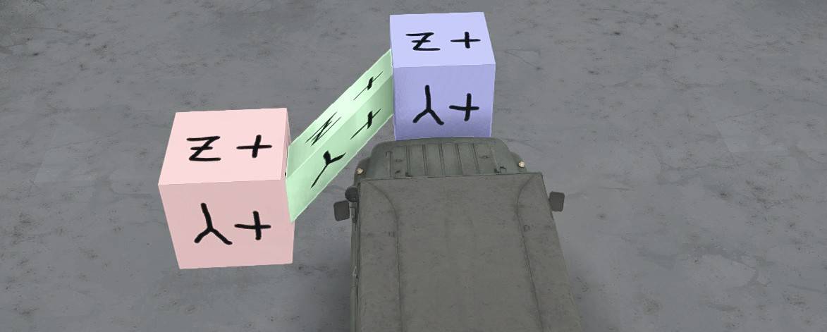
If you are porting a generic 3-D model from the internet to use in MudRunner, it might come as a single mesh. In that case, you can either cut the mesh into pieces to attach to body frames, or you can weight the mesh vertexes to the body frames as discussed here.
A deformable mesh is created by setting skin weights on its vertexes, where each weight is associated with a particular body frame. In the example image above, the vertexes on the left side of the green cube are weighted 100% to the red cube’s frame and 0% to the blue cube’s frame, and the vertexes on the right side of the green cube are weighted 0% to the red cube’s frame and 100% to the blue cube’s frame. If the cube mesh had additional vertexes in the middle, these could be weighted 50%/50% or any other choice of weights.
Vertexes are not limited to weights on only two bodies. A vertex can be weighted against any number of bodies.
Once any vertex has a skin weight, the mesh no longer defaults to moving as its parent body moves. Thus, if any vertex in a mesh has a skin weight, then every vertex in the mesh must be weighted to some body frame. Once a mesh has skin weights it no longer needs to be in any particular place in the frame hierarchy; it can be within any body’s hierarchy or no body’s hierarchy.
MudRunner does not support a collision detection mesh with skin weights. These meshes must be remain undeformed.
Blender Tips
In Blender, vertex skin weights are associated with armature bones. In order to associate skin weights with a body frame, you must constrain the bone to move with that frame. Once that is done, any motion of the body frame causes a corresponding motion of the constrained bone, which causes a corresponding motion in any vertexes weighted to that bone.
Caution: if the weighted mesh is a child (or any descendant) of any of the body frames it is weighted to, then moving the body frame in Blender will both move the mesh and distort the mesh, whereas you want it to distort without otherwise moving. For this reason it is best to clear the weighted mesh’s parent (moving it to the top level).
Ensure that Export Skin Weights is checked in the export dialog. This exports not only the skin weight values and associated bone names, but also the coordinate information needed to associate a change in body frame position/rotation with a change in the vertex position.
It is not necessary or useful to check Export Armature Bones; the bones would only show up in the DirectX file as empty frames.
Since the DirectX file can’t represent the bones themselves, you must ensure that the names of the bones in the skin weights match the names of the associated body frames.
If you are using the DirectX exporter built in to Blender, the exported skin weights name the bones as “{armaturename}_{bonename}”, and so you must name your body frame accordingly. E.g. if the armature is named “Armature” and the bone is named “crane”, then the body frame should be named “Armature_crane”.
If you are using my custom exporter for MudRunner, it has a Discard Armature Name option which is checked by default. In that case, you only need to name each bone the same as its associated body frame. E.g. the bone and body frame would both be named “crane”. My custom exporter is described in the “MudRunner Exporter for Blender” section of this guide.
Blender Instructions
There is a lot of information available on the internet about rigging armature, bones, and skin weights for Blender. Too much information, really, when you only want to know the subset usable by MudRunner. And MudRunner has its own quirks about how it expects the bones to be rigged. So although I don’t generally give detailed Blender instructions in this guide, I’ll make an exception here.
All of this is most easily performed when the model is otherwise complete, but it generally isn’t difficult to adjust the model after bones and skin weights have been set.
Create bones with the same name as the body frames
All bones should be created within a single armature. The location of the armature in the hierarchy doesn’t matter. The top-level is a natural location for it.
To add a new armature:
- In object mode, shift-A → Armature → Single Bone (or Add → Armature → Single Bone)
To add a new bone to an existing armature:
- Select the armature and select Edit Mode
- shift-A (or Add → Single Bone)
Rename the bone to match its corresponding body frame:
- Double click the bone in the outliner, or click its name in the Properties editor → Object tab.
Constrain each bone to its associated body frame
Create the constraint:
- Select the bone and go to Pose Mode (ctrl-tab)
- In the Properties editor, select the Bone Constraints tool (icon of a bone and chain link)
- Select Add Bone Constraint → Copy Transforms
- Target: <select body frame>
The distortion applied to vertexes is based on the difference between the bone’s pose position and its rest position. Once you’ve constrained the bone’s pose position to match the body frame, set that position as its rest position:
- ctrl-A → Apply Pose as Rest Pose
Now, moving the body frame (directly or by moving any of its ancestors) also moves the bone while the armature is in pose mode. If you want the new body frame location to be the default, select the armature and apply the pose as the rest pose again.
Deform a visual mesh based on bone/frame movement
Add the deform modifier to the mesh:
- Select the mesh in object mode
- In the Properties editor, select the Modifiers tool (wrench)
- Add Modifier → Deform → Armature
- Object: <select armature>
- Don’t touch the remaining settings for the modifier.
- Do not click Apply; that causes the modifier to be removed.
Blender associates skin weights with vertex groups, and it associates vertex groups with bones of the same name. Add each bone name as a vertex group name for the mesh:
- In the Properties editor, select the Data tool (triangle)
- In the Vertex Groups tab:
- Click “+”
- Rename the newly added group by double clicking it. Name it the same as the bone.
Repeat for all relevant bones.
Paint the skin weights onto the vertexes:
- Change to Weight Mode (ctrl-tab)
- Select a vertex group (bone) from the list of vertex groups in the Data tool.
- The Tools tab at the left has the relevant painting properties such as weight and brush radius.
- It’s easier to see the paint with Viewport Shading: Solid.
- Paint vertexes with left-click & drag in the 3-D view.
- Return to Object Mode (ctrl-tab again)
If the total weights for any vertex is more or less than 1.0, the exporter will normalize them for you.
Remember that once the deform modifier is applied to the mesh, all vertexes in the mesh must have a non-zero weight to at least one bone.
Export with Skin Weights enabled.
You don’t need to export Armatures! When skin weights are enabled, the exporter will include an unnecessary empty frame representing the armature. But it won’t export the bones themselves, and you don’t need it to since we’re weighting the mesh vertexes to body frames, not bones.
Custom Grass
This section assumes that you are familiar with creating a custom static model as described in the Custom Static Model sections.
Grass is a special type of 3-D model that can be included in great quantities in your map by using distributions and/or by attaching it to a material. Grass does not support collision detection, but instead is distorted automatically by wind and ground disturbance. Grass also does not support shadows or self-occlusion.
Grass requires the following files:
{mod directory}/meshes/grass/{name}.x contains the 3-D model.
{mod directory}/meshes/grass/{name}.xml specifies the appearance of the grass (mesh XML).
{mod directory}/textures/grass/ contains the textures for the grass.
{mod directory}/classes/grass/{name}.xml specifies the physics and distribution properties of the grass (class XML).
I’ll describe these files one at a time below.
Grass cannot be placed individually; it can only be placed as part of a distribution. To distribute your custom grass, you’ll need a custom distribution brush, described in the Custom Grass Distribution Brush section. Once you have a grass distribution brush, you can also attach your custom grass to a material using the GrassBrush property as described in the Custom Material section.
3-D Model
Create the 3-D model for the grass with a 3-D modeling tool and export it in DirectX format for use in MudRunner.
Unlike a “model” object as described in the Custom Model section, a “grass” object does not require a collision-detection mesh. I.e. no “cdt” mesh is required.
The grass model can include any number of visible meshes. These meshes can be at any level of hierarchy and can have any name that does not start with “cdt”. (A mesh that starts with “cdt” is discarded by the display engine.)
Grass should be relatively small to avoid looking unnatural as a truck passes through it. The grass model should be rooted at Y=0 in order to be attached to the ground.
For good performance when placing lots of grass, keep your polygon count as low as possible. As an example, the built-in grass_long model appears to have only 4 two-sided polygons.
Blender Tips
Unlike for a custom model, MudRunner does not support hierarchical transforms or rotations in a grass model.
For grass models, I recommend my custom DirectX exporter. It can export DirectX files that MudRunner can read, even for grass models with arbitrary transformations in the object hierarchy. Check out the “MudRunner Exporter for Blender” section of this guide. If you use my exporter, you can skip the rest of this section.
If you instead use Blender’s built-in DirectX exporter, I recommend the following steps in order to export successfully:
- Put all objects in a single top-level container. [Left click and shift left click all objects in the outliner, adding the top-level container object last, and press ctrl-P: Set Parent to Object (Keep Transform).]
- Set the top-level container’s X rotation to 90° (so that the child objects have their local Y coordinates pointing up).
- Set the top-level container’s Z scale to -1.0 (so that the child objects have their local Z coordinates pointing “south”).
- Select all objects. [Ctrl left click the top-level container’s icon in the outliner.]
- Apply all transformations of selected objects to the underlying meshes. [Ctrl-A: Apply Location, then Ctrl-A: Apply Rotation & Scale.]
- Export your model.
- Undo your changes until your models are flipped correct upright. [Ctrl-Z.]
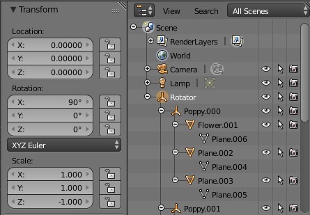
Select File→Export→DirectX to export. Click to clear the checkbox for “Export Selected Objects Only” so that all meshes are exported. Also switch the coordinate system to “Right-Handed”. (Note that this is opposite to the coordinate system used for models.)
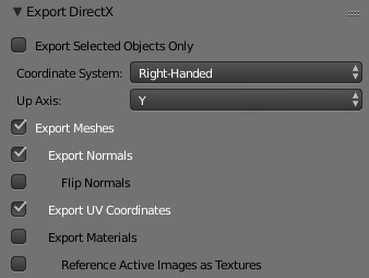
Blender doesn’t remember these settings from session to session, so you’ll need to remember to update them every time.
The right-handed coordinate system is required if you use single-sided polygons so that they face the correct direction. The coordinate system doesn’t matter if you use two-sided polygons.
The “Up Axis” export setting doesn’t matter since it only changes the top-level transformation matrix emitted by the exporter, which MudRunner ignores anyway.
The Blender exporter converts punctuation and spaces in names to “_”. Keep this in mind when using the MeshParts property in the mesh XML.
View the DirectX Model
The MudRunner Editor has a model viewer built in. However, this viewer applies a capricious rotation to a grass model, turning it to a strange upside-down angle. For this reason, I find it much easier to view the grass as part of a map.
Grass Mesh XML (Material)
Examples are in MeshCache.zip/grass_*. The cached mesh files contain multiple file types in one file, but with the right file viewer you can browse the XML contents at the beginning of the file (and lots of binary junk later in the file).
Your mesh XML file goes in {mod directory}/meshes/grass/{name}.xml
<CombineXMesh Type="Grass" {properties}>

{plantmesh}

{materials}

</CombineXMesh>
CombineXMesh Properties
Type="Grass"
This type is required for grass models.
File="{name}"
Normally your DirectX model, mesh XML, and class XML must all have the same base filename. However, this property allows multiple MudRunner grasses to share the same DirectX model. E.g. if _ball2.xml includes File=”_ball”, it uses _ball.x as the DirectX model.
Wind Animation
By default, MudRunner applies an animation effect to your grass model so that it appears to blow in the wind. This effect shears the model so that the ground plane remains where it is, while the upper parts of the model move around.
The wind effect can be disabled by adding a PlantMesh tag with the property WindAnimation=”false”. E.g.
<CombineXMesh Type="grass">

<PlantMesh WindAnimation="false" />

{materials}

</CombineXMesh>
Materials
When you exported your grass to DirectX, your textures were not included. You can re-attach textures to your grass using one or more Material tags.
<CombineXMesh Type="grass">

<Material {Material properties} />

[...]
</CombineXMesh>
One or more Material tags can be included with your grass in order to apply any number of textures/colors to different parts of it. Material properties are described below.
MeshParts="{name}"
Specifies a portion of the 3-D model for which to apply the material. The MeshParts property must specify the direct containing frame of a mesh, not a higher hierarchical level. Multiple names can be specified, separated by commas. If MeshParts isn’t specified, the material is the default material for the grass.
If a mesh was modeled with multiple materials (and the material list was exported), then the mesh XML can specify a material for each part of the mesh that had a different material. These mesh parts are named in the MeshParts property as “{frame} {partnumber}”, e. g. “poppy 0”. The part number can be verified in the model viewer, described in the previous section. If the part number isn’t specified in the MeshParts property, part 0 is assumed.
DiffuseMap="grass/{filename}"
The DiffuseMap is a standard texture to apply to your grass, using the UV mapping that you set up in your 3-D modeler. Your texture file can have any common image file type and associated extension, e.g. “{name}.png”. As with other textures, ending the name with __d or __d_a is recommended.
Note that the path to the file assumes {mod directory}/textures. Usually you’ll put your texture in the grass subdirectory as indicated above, but it can be anything, e.g. if you’d like to reuse a texture that is also used for a material.
Example textures can be found in TextureCache.zip/grass_*.dds
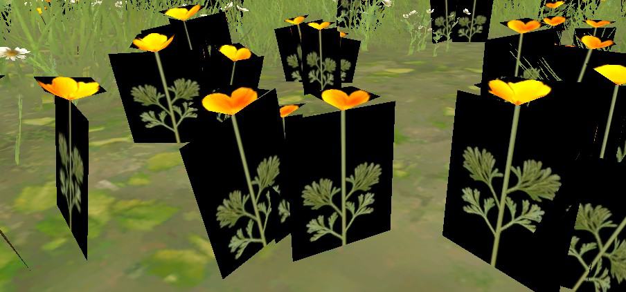
BTW, a normalmap or specularmap is not supported by grass.
DiffuseMultiplier="{color}"
Shifts the pixel colors by the specified color. This effect can be applied on top of a texture or on top of the default white. The color is specified as described in the “Colors” section of this guide. A standard white color means “no change”. Darker, brighter, or tinted colors modify the DiffuseMap texture or the default white as per the color.
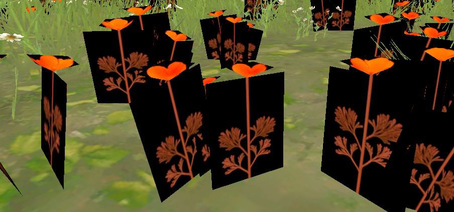
AlphaKill="true"
Makes the mesh transparent where the texture is transparent. By default the texture’s alpha channel is ignored. Unlike models, grasses support partially transparent pixels in the texture. MudRunner converts these to fully transparent or opaque, whichever is a better match.
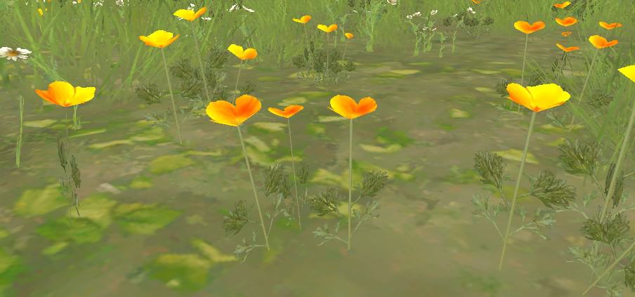
TwoSided="true'
Makes the mesh visible from both sides. Most of the built-in grass models use TwoSided polygons with AlphaKill to display simple two-dimensional grass with irregular outlines.
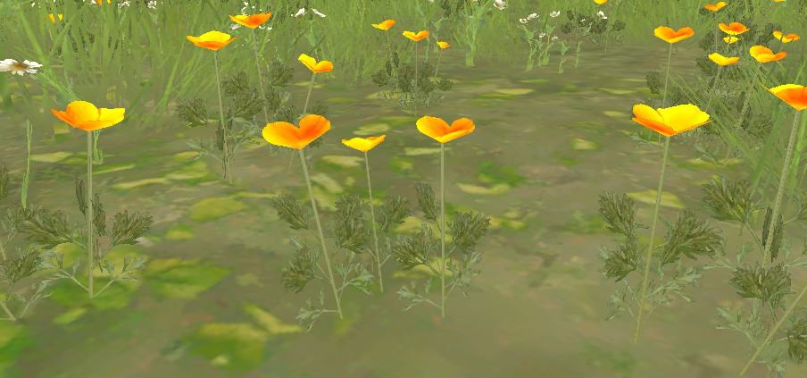
Grass Class XML (Distribution)
Examples in Media/class/grass/*.xml
Your file goes in {mod directory}/class/grass/{name}.xml
<GrassBrand {properties} />
Grass class information is kept in memory whenever the grass is present on the map, so to re-read the class XML file you must reload the map.
PlantingGroup="{name}"

PlantingMinSpacing="{value}"
These are much the same as for plants (described in the Custom Plant Distribution Brush section), except a grass can only be in a single planting group. (Notice the different names for PlantingGroup vs. PlantingGroups.) The other difference is that grasses do not check the minimum spacing between grasses within the same distribution brush. They only check the minimum spacing with respect to other distribution brushes or other distributions.
NotAtThickGrass="true"
This property is associated with grasses listed in Group A in the Materials Reference section.
This property is ignored, although you’d expect that it would prevent the grass from being distributed on a material that has IsThickGrass=”true”. Instead, the editor appears to exclude debris_chunks, ground_leaves, and strobiles based on their names. E.g. a custom grass with “strobiles” in its name is excluded. Grasses with non-matching names are not excluded. The exact scope of name matching is beyond my ability to predict.
IgnoreNoGrass="true"
This property is associated with grasses listed in Group B in the Materials Reference section.
This property is ignored, although you’d expect that only grass with this property is allowed to be distributed on a material that has NoGrass=”true” or a road overlay that has MaskPlants=”true”, and other grasses are excluded. Instead, for exclusive materials and road overlays, the editor appears to allow debris_chunks, debris_stones, ground_leaves, and strobiles based on their names. E.g. a custom grass with “strobiles” in its name is allowed. Grasses with non-matching names are excluded. The exact scope of name matching is beyond my ability to predict.
ApplyScaleMask="true"
By default, I estimate that grasses use the equivalent of MinSize=1.0, MaxSize=1.0, and ScaleRandom=0.15 (as described in the Custom Plant Distribution Brush section). When ApplyScaleMask=”true”, they use the equivalent of MinSize=0.95, MaxSize=1.13, ScaleRandom=0.45. In other words ApplyScaleMask allows the distribution’s scale channel to have a (small) effect, and it also greatly increases the randomness in the grass size.
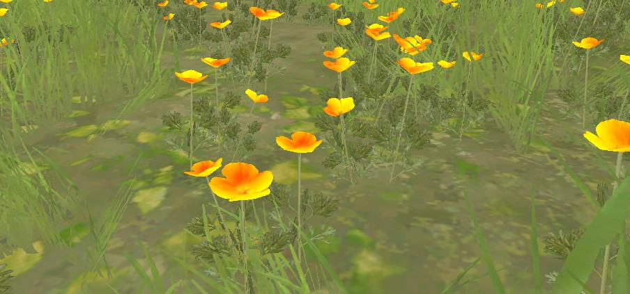
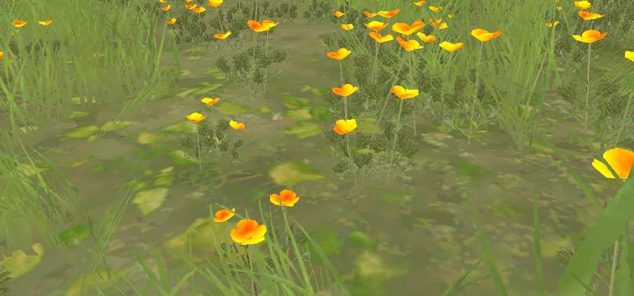
Custom Plant
These sections build upon the concepts introduced for dynamic models and for grasses.
MudRunner optimizes plants to perform well even when placed on the map in large numbers. Like grass, plants can automatically sway in the breeze. Like models, the player’s truck can interact with plants and potentially break them. A broken plant can simply sink into the ground and fade away, or instead it can be “chunked” into smaller parts. Plants support lights and self-illumination. Plants are the only object that support winch points that a truck can attach to.
For each individually placed plant and each plant placed by a distribution, the MudRunner Editor increases the height of the terrain by a small amount at the XZ location of the plant’s origin. The height increase is based on the size and scale of the plant. Similar to height effects from mud and road overlays, the height increase is not a permanent change to the geometry, but an effect applied only when the plant is present. The height effect becomes visible when Rebuild Terrain is selected.
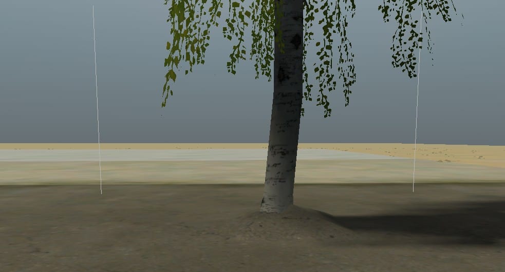
A MudRunner plant requires the following files:
{mod directory}/meshes/plants/{name}.x contains the 3-D model.
{mod directory}/meshes/plants/{name}.xml specifies the appearance of the model (mesh XML).
{mod directory}/textures/plants/ contains the textures for the model.
{mod directory}/classes/plants/{name}.xml specifies the physics of the model (class XML).
I’ll describe these files one at a time below.
In addition, the MudRunner editor typically creates a billboard texture for you:
{mod directory}/billboards/{name}__d_a.dds
3-D Model
The 3-D model for a plant should contain exactly one visual mesh in a frame exactly named “plant”. This single mesh may contain multiple materials. As with grass, any geometry transformations are ignored in the hierarchy leading to the plant’s visual mesh. Also like grass, MudRunner will automatically warp this mesh as if it is blowing in the wind.
The 3-D model can also include any number of cdt frames, the same as for models. Also like models, a cdt frame can have rotation and translation in its hierarchy, but not scaling.
When MudRunner first encounters a plant and adds it to its mesh cache, it creates a billboard for it. If MudRunner can’t find a visual mesh exactly named “plant”, you’ll get error messages.
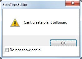

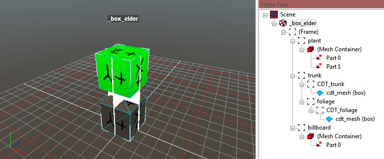
The billboard planes display as white in the model viewer, but MudRunner also creates a billboard texture at the same time as it creates the billboard planes. It does this by snapping a picture of your plant from the east, north, west, and south sides, and creating a texture with all of these images. The billboard texture is given a resolution appropriate for the size of the plant; i.e. a large plant gets a higher-resolution texture. The texture includes all visual effects described by the mesh XML, such as color multipliers and self-occlusion. The billboard texture is saved to {mod directory}/billboards/{plantname}__d_a.dds
The billboard planes and texture are used in place of your usual model when viewing the plant at a long distance.
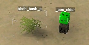
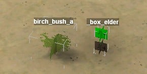
If you delete the billboard texture file while the plant is cached in the mesh cache, MudRunner will complain about the missing texture. Delete the file from the mesh cache or touch the .x or .xml files to regenerate the mesh cache and the billboard texture.
Hand Create a Billboard
The game creates a billboard for you, so there is very little reason to create one for yourself, but you can do so if you want to. With an explicit billboard, wind effects are disabled, and occlusion is simplified. Perhaps these effects can be mitigated, or perhaps there are other adverse effects that I didn’t discover. I didn’t look into it very deeply.
To create your own billboard, create the billboard polygons in your mesh in a frame exactly called “billboard”. A Material tag cannot be applied to the billboard mesh. Instead, this mesh is implicitly TwoSided=”false”, AlphaKill=”true”, and its DiffuseMap is loaded from billboards/{plantname}__d_a.dds
Because the billboard mesh is one sided, make sure to create polygons facing in all directions. This mesh doesn’t need to be the simple four-plane crossing model automatically created by MudRunner, but you should keep it as simple as possible to keep performance high.
It may be easiest to generate the optimized billboard texture file by first creating the billboard model as a separate model or plant, then copying the optimized DDS file from the texture cache to your billboards directory.
If you accidentally create a plant with a “billboard” mesh but not a “plant” mesh, you get a different error message.
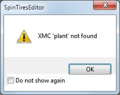
Blender Tips
Because a plant supports only a single visual mesh, you will need skin weighting to attach the visual mesh to multiple CDT bodies (as described in the Model Deformation section). You might find it easiest to create the plant mesh as separate meshes, with different materials as needed. Then, join the meshes into one (with ctrl-J) before exporting.
The “plant” frame can be anywhere in the hierarchy, but it makes the most sense to put it at the top level, a sibling to the top level CDT body frame. Any transformations in the plant frame’s hierarchy must be propagated to the plant mesh using ctrl-A (apply).
The body hierarchy can also be flattened, but it’s easier to set up the class XML if you keep the frame rotations and translations in the hierarchy. Otherwise you’ll need to specify the PivotOffset of each Ragdoll constraint relative to the plant origin, and IsCapsuleCDT may be tough to get to work.
If you use my custom DirectX exporter for Blender, see the ‘MudRunner Exporter for Blender’ section for tips for plants.
Plant Physics Limitations
A plant has different physical properties depending on whether it is in its normal state, it is broken, or it has been spawned as a plant chunk from a broken plant. Specific details about broken plants are described in the corresponding sections.
By default, a plant’s physics are enabled only when the truck is touching or nearly touching one of the plant’s collision detection meshes, or when the plant has sufficient residual velocity or forces after a truck encounter. When the truck has moved away and the plant has stopped moving, the plant’s physics are disabled.
When a plant’s physics are enabled, the visual mesh is weighted to the body frames and reacts accordingly. When a plant’s physics are disabled, the plant’s bodies reset to their default position. Therefore, it is useful to put strong springs and well-tuned dampers on the plant so that it returns to its rest position as quickly as possible. It is also useful to surround the plant with foliage so that the plant’s physics remain enabled while the truck is within the foliage, giving time for the non-foliage parts to return to their rest position. A collision detection mesh with Collisions=”None” can also serve this purpose.
When a plant’s physics are disabled, the plant’s visual mesh is displayed without regard to the orientation of the body frames. If the plant snaps from one position to another when the truck approaches, it is because the default visual mesh position doesn’t correctly match its position when weighted to the body frames. If that happens, check your model hierarchy and export settings. (This is different than when the plant snaps between positions when the truck moves away; this may simply be the plant’s bodies returning to their rest position as described in the previous paragraph.)
The billboard is always static. It doesn’t sway in the wind, and it isn’t influenced by body physics. Of course, the difference shouldn’t be noticeable for any normal plant at the distance at which the billboard is used, but the static nature of the billboard can be seen in the model viewer.
By default, gravity has no effect on the plant. Only forces applied by the truck and by the plant’s constraints can move the plant. Gravity is applied only in certain circumstances as described in the sections below.
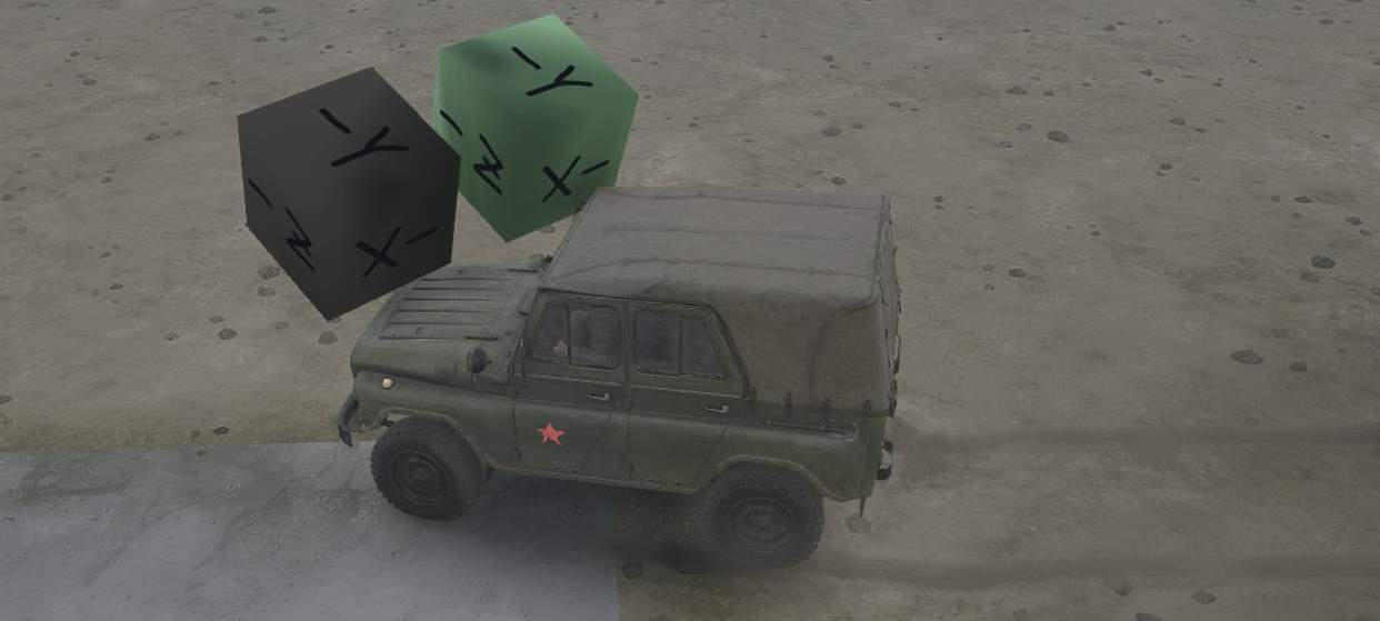
If a plant’s body moves more than ~10-30 meters from its original position, its physics are disabled regardless of other factors. Plants don’t have any equivalent to the DynamicModel property used by models.
Although no built-in plant assets use them, the Hinge and Prismatic constraints do work. However, the Motor tag has no effect for Hinge and Prismatic constraints. Therefore, I consider the Hinge and Prismatic constraints to be unsupported and recommend against using them.
Plant Mesh XML (Material)
Examples are in MeshCache.zip/plants_*. The cached mesh files contain multiple file types in one file, but with the right file viewer you can browse the XML contents at the beginning of the file (and lots of binary junk later in the file).
Your mesh XML file goes in {mod directory}/meshes/plants/{name}.xml
<CombineXMesh Type="plant" {combinexmesh properties}>

<PlantMesh {plantmesh properties} />

<Material {material properties} />

[...]
</CombineXMesh>
Effects of properties in the mesh XML file can be seen in the model viewer. This includes effects of the PlantMesh tag.
CombineXMesh Properties
Type="Plant"
This type is required for plants.
File="{name}"
Behaves the same as the equivalent property for models.
PlantMesh
The optional PlantMesh tag contains properties that affect the look of the entire plant.
WindAnimation="false"
By default, MudRunner applies an animation effect to the foliage your plant so that it appears to blow in the wind. This effect distorts the plant’s vertexes so that the ground plane remains where it is, and the upper parts of the plant sway side to side and up and down. This is regardless of the shape and structure of the plant bodies and constraints. Each vertex moves somewhat independently, so make sure that the various faces of your plant model share vertexes as much as possible so that they move together.
The wind effect can be disabled with the property WindAnimation=”false”. The effect is also disabled for non-foliage. See the IsFoliage property below.
The MudRunner Editor samples the height of the terrain, models, and plants in order to draw the 3-D navigation map. If the sample finds a plant at a point, then the point sways in the wind on the navigation map. This happens regardless of the WindAnimation setting.
OcclusionIntensity="{value}"

OcclusionRadius="{value}"
These values affect volumetric self occlusion. I can’t really figure out how the values work other than to say that if either value is 0, self occlusion is disabled, and self-occlusion increases with increasing values. If very small occlusion values (such as 0.05 for each) cause a portion of the model to go entirely black, it is probably because 3-D model hierarchy or visual mesh weighting is broken in some way. Debug your model before trying to fix your occlusion.
Self-occlusion effects change based on the rotation and tilt of the plant. The billboard texture is created with self occlusion applied in the default orientation.
Self occlusion appears to effect non-foliage more than foliage. (See the IsFoliage property for PlantMaterial below.)
Don’t confuse self occlusion with ground occlusion, discussed in the Plant Class XML section.
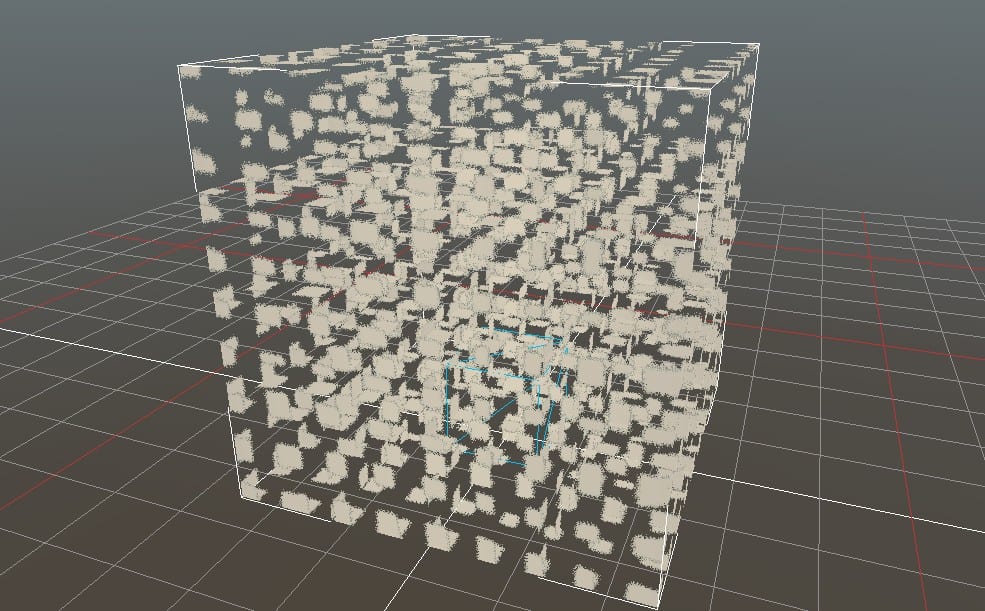
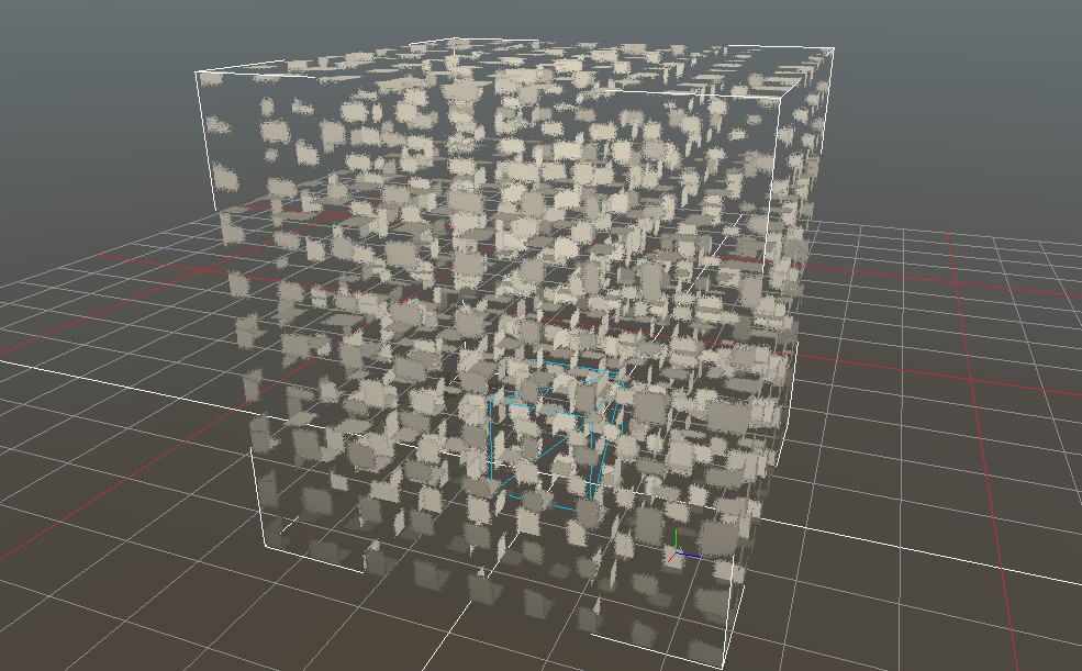
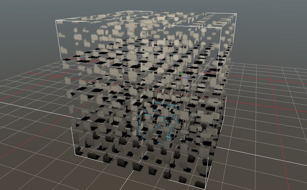
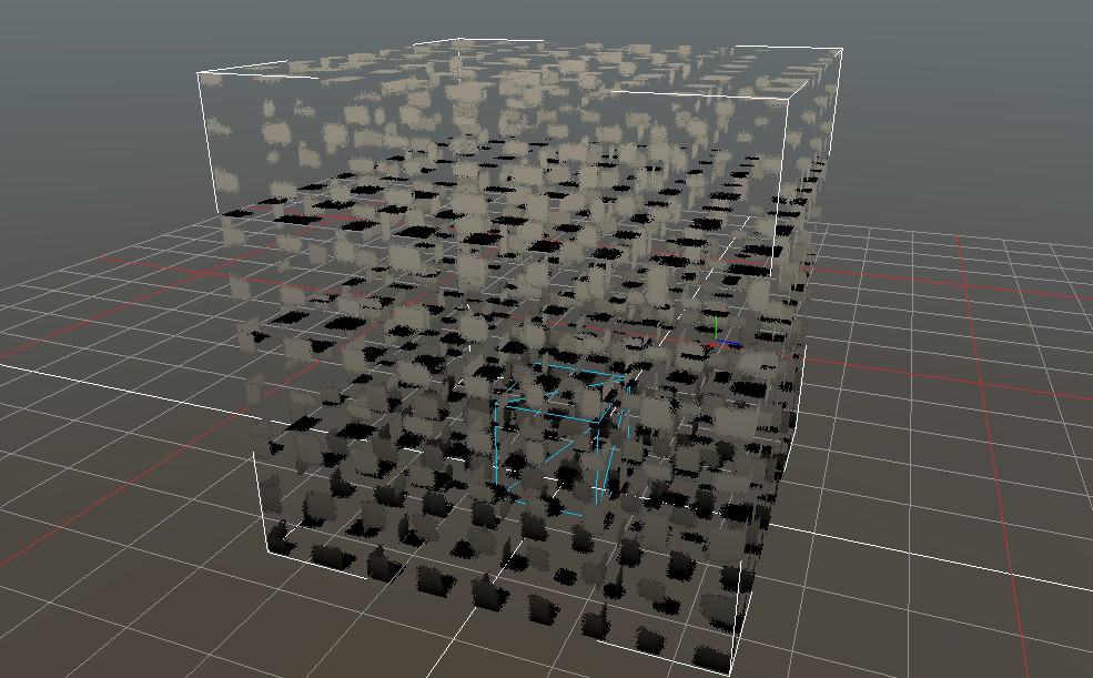
When you exported your plant to DirectX, your textures were not included. You can re-attach textures to your model using one or more Material tags.
One or more Material tags can be included with your plant in order to apply any number of textures/colors to different parts of it. Material properties are generally the same as for models, with exceptions as noted.
MeshParts="{name}"
Same as for models.
DiffuseMap="plants/{filename}"
Same as for models.
The path to the file assumes {mod directory}/textures. Usually you’ll put your texture in the plant subdirectory as indicated above, but it can be anything, e.g. if you’d like to reuse a texture that is also used for a material.
Example textures can be found in TextureCache.zip/plants_*.dds
BTW, a normalmap or specularmap is not supported by plants.
DiffuseMultiplier="{color}"
Same as for models.
IllumMap="{plants/{filename}"
IllumMap brightens up sections of the plant using the same UV mapping as DiffuseMap. IllumMap applies only at night. It increases the brightness of sections of the model that naturally have a light color, but it has no effect on black sections of the model. The function appears to be something like this: “illuminated color = normal color * (1 + IllumMap color)”.
IllumMap is supported only for plants. It is not supported for models.
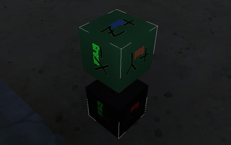
AlphaKill="true"

TwoSided="true"

BacksideLighting="{value}"
Same as for models.
NormalMap="models/{filename}"

DetailMap="models/{filename}"

Blending="additive"

IsSfx="true"
Not supported by plants.
PlantMaterial Tag
The Material tag can optionally include a PlantMaterial tag. E.g.
<Material {material properties}>

<PlantMaterial {plantmaterial properties />

</Material>
PlantMaterial properties are as follows.
IsFoliage="true"
Foliage is subject to wind animation. Foliage also gets less self-occlusion than non-foliage. There may be other effects, but I haven’t been able to determine them.
IsNearClip="false"
By default, portions of a plant that are very close to the model are made semi-transparent so that the player’s vision isn’t blocked. IsNearClip=”false” disables this.
In the example below, IsNearClip=”false” has been set for the green box in the second image.
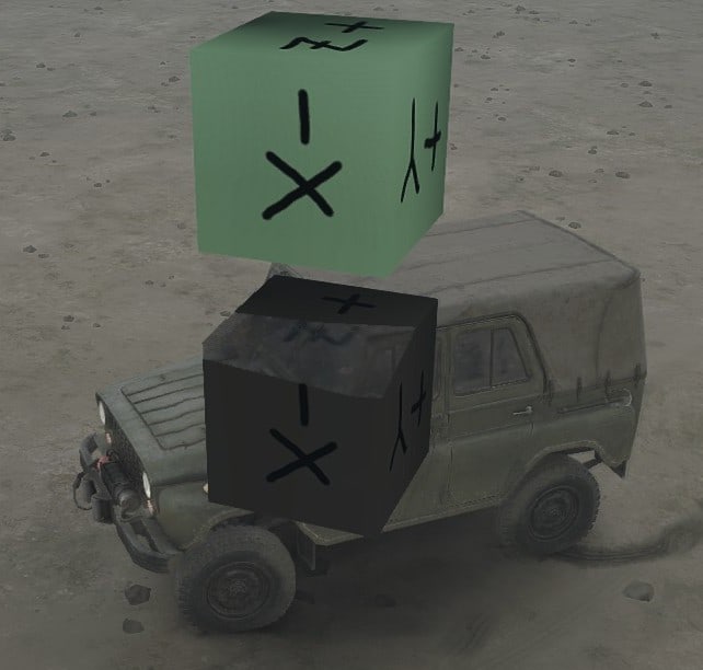
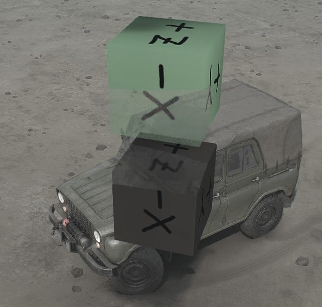
Plant Class XML (PlantBrand)
The plant class XML file contains a huge amount of data spread among a number of tags.
<PlantBrand {plantbrand properties}>

<Body {body properties}>

{...}

</Body>

<ChunksBreak {chunksbreak properties} />

<Landmark {landmark properties} />

<GameData>

<WinchSocket {winchsocket properties} />

{...}

</GameData>

<Occlusion {occlusion properties} />

<StaticLights>

<StaticLight {staticlight properties} />

{...}

</StaticLights>

</PlantBrand>
All properties in the class XML file are kept in memory whenever the plant is present on the map, so to re-read them you must reload the map. Plant template files are always kept in memory, so to re-read a template file you must entirely quit the editor/game. For most properties, you must also Rebuild Terrain to see the modified effect.
Whereas the MudRunner Editor checks and displays warnings if values are incorrect in the model class XML file, it displays almost no information at all about the plant class XML file except for gross syntax errors in the XML. This makes debugging a custom XML file much more difficult. I encourage you to practice with custom models (with a deformable mesh) before making a custom plant.
The PlantBrand properties are described below. Other tags are described in the following sections.
PlantBrand Properties Affecting Distribution
When customizing properties related to plant density, beware to not create so many plants that it slows down the rendering engine or the physics engine. Having said that, I have no idea how much the current density limits are intended to avoid performance bottlenecks vs. simply creating a pleasing plant distribution.
PlantingGroups="{names}"

PlantingMinSpacing="{value}"
In order for the plant to be placed as part of a distribution, the plant must be at least {value} meters away from all other plants that share a planting group. The MudRunner Editor actually checks the PlantingMinSpacing of both plants when checking the distance between them. This includes plants in other distributions and even individually placed plants. PlantingGroups is a comma-separated list of names. The main purpose of the minimum spacing to to avoid plants visually growing through each other.
The built-in planting group names and the plants in each group are listed in the Distribution Reference section of this guide. In addition to the names used by built-in plants, you can use any other group name you wish. If PlantingGroups is not defined, the plant is part of no planting groups, and so no minimum spacing is enforced.
CheckNoGrass="true"
This property is associated with plants listed in Group B in the Materials Reference section. Unlike the similar IgnoreNoGrass property for grasses, the CheckNoGrass property is correctly used by the editor.
When CheckNoGrass=”true”, the plant is not distributed on a material that has NoGrass=”true” nor on any road overlay.
When CheckNoGrass=”false” (the default value), the plant is allowed to be distributed on any material or on a road overlay that has MaskPlants=”true” (but never on a road overlay that has MaskPlants=”false”).
PlantingOffsetY="{value}"
Specifies a vertical offset for the plant when it is placed via a distribution. The default value of 0 places the origin of the plant exactly on the terrain. A positive value is higher. A negative value is lower.
This property isn’t the same as simply moving the plant origin within its model. When the plant isn’t vertical (e.g. when its distribution specifies a positive Perpendicularity), PlantingOffsetY moves the plant directly in the world’s Y axis, whereas a different plant origin would move the plant at an angle.
DistSkipPercentage="{value}"
As far as I can tell, this property isn’t used.
PlantBrand Properties Affecting Appearance
Reminder: the map must be reloaded to reread the class XML file.
LocalYOcclusionOffset="{value}"
The occlusion of the player’s truck is this much lower on the plant than usual. I.e. positive values cause the truck’s occlusion to be lower on the plant, and negative values cause it to be higher. The default is 0.
DisableShadows="true"
Causes the plant to not cast a shadow during the day. It still casts a shadow at night.
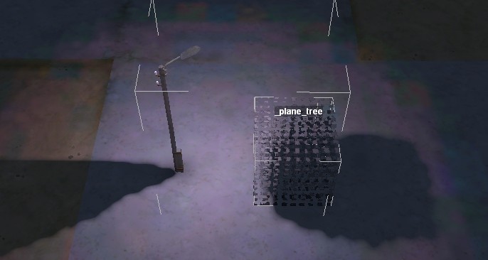
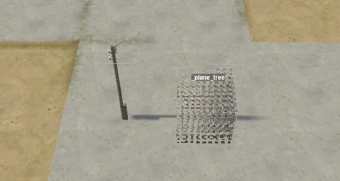
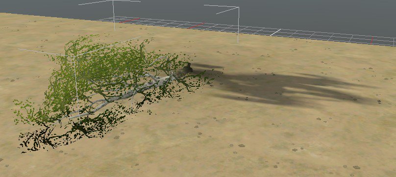
Nighttime shadows are calculated using the plant’s actual orientation.
UseDirtTint="true"
When UseDirtTint=”true”, the plant is tinted gray-green when its origin is over a tinted portion of terrain. When UseDirtTint=”false” (the default), the plant is instead tinted brown when its origin is over a tinted portion of terrain.
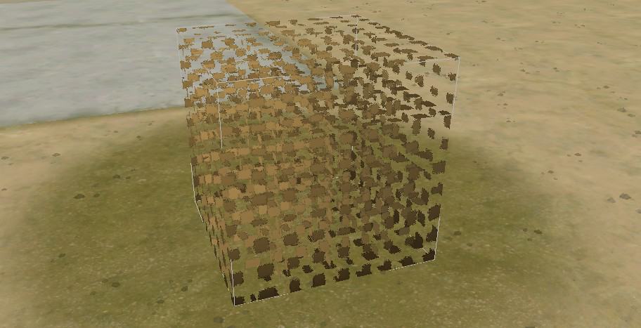
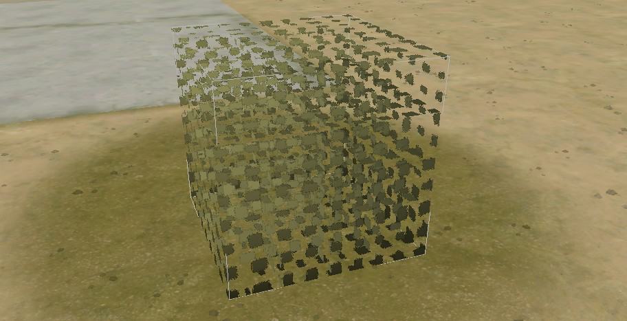
These properties are described in the next section.
Properties for a Broken Plant
If a Constraint tag’s BreakOffThreshold property is exceeded, the plant is “broken”. Broken plants are described in this section.
On the other hand, if a ChunksBreak tag’s Threshold property is exceeded, the plant is “chunked”. Chunked plants are described in the next section.
When a broken plant is moved or disappears, its shadow remains, so consider DisableShadows for a breakable plant.
The following PlantBrand properties specify the behavior for broken plants.
DeleteOnBreak="true"
Causes the plant to be deleted as soon as it is broken.
By default, the plant behaves according to the AttachToGround property below.
AttachToGround="false"
If AttachToGround=”false” and a plant’s top-level constraint to ground is broken, the plant can be pushed around the terrain. The plant remains subject to physics distance limits.
If AttachToGround=”false” and any constraint is broken, then when the plant’s physics are disabled, the plant resets to its original position, unbroken. (This does have a certain appeal when testing the break properties of a plant.)
AttachToGround=”false” is generally not useful for a normal plant, but it can be useful for plant chunks. See the ChunksBreak tag’s Brands property for details.
If AttachToGround=”true” and a plant’s top-level constraint to ground is broken, then a new constraint is created in its place to hold the plant’s origin in place, but not necessarily upright.
If AttachToGround=”true” and any constraint is broken, then when the plant’s physics are disabled, the plant disables collisions and slowly sinks into the ground before disappearing.
Regardless of the AttachToGround property, breaking any parent-child constraint causes gravity to be enabled for the child body only. (For this purpose, the top-level body is the child for its constraint to ground.) This limited gravity generally looks fine as long as the plant has a typical distribution of mass, with most mass at the base and less mass at the extremities.
Breaking a cross constraint causes gravity to be enabled for both bodies, and perhaps for the entire plant.
BreakType="{name}"
The BreakType specifies what additional effects are applied when the plant is broken at its connection to ground. If the plant is broken elsewhere, the BreakType effects are not applied.
For BreakType=”BigTree”, breaking the plant causes the sound of a large tree cracking and crashing. A shower of dirt is also thrown into the air from the plant’s origin. The height of the shower of dirt is somewhat influenced by the scale of the plant.
BreakType=”SmallTree” is similar, but the sound is reduced in volume and duration, and the shower of dirt is smaller.
For BreakType=”Mushroom”, there is a squishing sound, and a small cascade of orange fragments erupts in a small white pool of slime.
If the BreakType is not one of the above names or is not specified, the plant breaks without any fanfare. The built-in plant pumpkin_a includes BreakType=”Pumpkin”, but this is not a supported value for BreakType.
Media/media.xml maps break types to sounds, and the sound files can be found in Media/sounds/env. There are multiple sound files for each break type, which I assume the game randomizes among. Note that media.xml includes some values corresponding to the ChunksBreak Handler property, but they don’t actually do anything.
Visual effects are specified in Media/classes/particles/*.xml. I suspect that these filenames are hard-coded into the game, so there is no place to read the exact mapping of BreakType to particle effect.
The sound files and particle effect XML files can be browsed for understanding, but I have not investigated whether they can be modified and packaged in a mod.
Properties for a Chunked Plant
If a ChunksBreak tag’s Threshold property is exceeded, the plant is “chunked”. Chunked plants are described in this section.
On the other hand, if a Constraint tag’s BreakOffThreshold property is exceeded, the plant is “broken”. Broken plants are described in the previous section.
When a plant is chunked, its shadow remains, so consider DisableShadows for a chunkable plant.
The following ChunksBreak properties specify the behavior for chunked plants. The ChunksBreak tag is a child of the PlantBrand tag in the plant class XML file.
Threshold="{value}"
Specifies a threshold at which a flex spring breaks and triggers the ChunksBreak effect. This is measured very differently from the BreakOffThreshold in the Constraint tag. It appears that the flex spring has an initial resistance tuned to the weight of the body, but when the spring is stretched a certain distance, the resistance ramps up quickly so that it can resist an arbitrary external force. The Threshold appears to be some measure of this extra resistance.
Note that if the body mass is significant, the initial resistance of the flex spring is correspondingly large. If this initial resistance is sufficient to entirely resist the truck before engaging the extra resistance, the Threshold will be impossible to reach even if its value is small. There is an exception when the constraint is attached to ground, in which case the extra resistance appears to be engaged immediately. For built-in plants with the ChunksBreak tag and a static root body, the mass of a foliage body is always less than 0.5. For built-in plants with the ChunksBreak tag and a dynamic root body (attached to ground with a constraint), higher masses are used.
When the Threshold is exceeded for any constraint, the plant disappears and plant chunks are created in its place per the properties below.
If the Threshold is 0 (the default), then the threshold is treated as infinite, and the ChunksBreak tag is effectively ignored.
Handler="{name}"
The Handler specifies what additional effects are applied when the plant is chunked. Unlike the similar PlantBrand BreakType, the ChunksBreak Handler property never triggers a sound. (Perhaps this is a bug.)
For Handler=”Bush” or “BirchBush” or “LyingSpruce”, breaking the plant into chunks causes a small shower of twigs to erupt from the plant’s origin.
For Handler=”Pumpkin”, breaking the plant into chunks causes a small cascade of orange fragments to erupt in a small white pool of slime.
If the Handler is not one of the above names or is not specified, the plant breaks into chunks without any fanfare. Some built-in plants use Handler=”Cane” and Handler=”Mud”, but these names are not supported.
Brands="{names}"
Specifies the plants that are created as “chunks” of the original plant. Multiple names can be specified, separated by commas, in which case MudRunner randomizes among them.
Brands cannot specify a grass, only a plant. If no plants are specified (the default), no chunks are created.
If the created plants have PlantBrand property AttachToGround=”true”, they are created as broken plants which sink into the ground as soon as their physics are disengaged.
More typically, the created plants have PlantBrand property AttachToGround=”false”. They follow normal physics rules (including gravity). Unlike normal plants with AttachToGround=”false”, plants created as chunks do not reset their position when their physics are disengaged. Instead, the chunks remain indefinitely even if the player drives far away before returning. However, like other plants with AttachToGround=”false”, plants created as chunks abruptly disappear if pushed beyond their distance limit. Fortunately, this is less noticeable for a small plant chunk than for a full-sized plant.
SpawnAtEachBody="true"
I’m not quite sure what this does. Possibly it creates a chunk for each body, not including the top-level body, but it doesn’t appear to put them at the origin of each body. SpawnAtEachBody may be an old property that has been supplanted by the greater control of the properties below. If the Offsets property is specified, SpawnAtEachBody is ignored.
The default is to create a single chunk at the top-level body’s origin.
Offsets="{offsets}"
Specifies a list of 3-D offsets separated by commas, e.g. Offsets=”(-0.08; 0.02; 0),(0.05; 0.02; -0.08),(0.05; 0.02; 0.08)”. A chunk is created for each specified offset at twice the offset from the original plant’s final location (its origin in world space after its flex springs have been stretched). Each chunk is originally created in an upright position, but see SpawnAngMult below. Each chunk is created with a random orientation around its vertical axis.
If Offsets is left unspecified, the SpawnAtEachBody property is used instead, and the SpawnLinMult and SpawnAngMult properties below are ignored.
SpawnLinMult="{value}"
For each chunk created, the game computes a vector specifying its offset in the XZ plane only (ignoring the Y component of its offset). SpawnLinMult specifies a speed in meters/second.
Each chunk is created with a velocity of the SpawnLinMult speed in the direction of its XZ vector. The default value is 0, meaning that the chunk remains where it is created.
SpawnAngMult="{value}"
SpawnAngMult specifies a rotation velocity for each chunk in radians/second. The top of each chunk’s rotation is in the direction of the XY unit vector described with SpawnLinMult, above. The default value is 0, meaning that the chunk remains in its upright orientation.
Plant Bodies and Constraints
Plant bodies and constraints are exactly the same as model bodies and constraints except for the following exceptions and additions.
Changed Body Properties for Plants
GravityFactor="{value}"
No known effect. Gravity is disabled for plants by default. Gravity is enabled for a broken plant or a plant chunk, but GravityFactor has no effect for those cases, either.
The stump_a built-in plant specifies GravityFactor=”0″ for its bodies despite the property’s apparent lack of effect.
IsStaticSoil="true"
No effect. Driving on a plant never throws dirt clods, but it does generate dust (regardless of underlying material).
Added Body Properties for Plants
IsCapsuleCDT="true"
This property is very hard to make heads or tails of. The built-in plants use this property for sparse foliage. Certainly it allows the player’s truck to sometimes partially penetrate the collision detection mesh before the collision is registered. The behavior isn’t entirely consistent, but it appears that the front of the truck can penetrate the collision detection mesh by ~0.5 meters, whereas the back of the truck sometimes hits the collision detection mesh ~0.5 meters early. (Ignore the brown cube in the images below; I’ve turned off its collisions for experimentation purposes. The green cube has IsCapsuleCDT=”true”.)
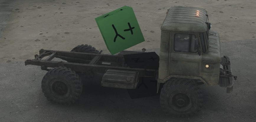
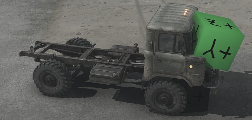
IsCapsuleCDT=”true” also allows a plant body to penetrate the terrain by ~0.5 meters, whereas a normal plant body attempts to stay out of the terrain entirely.
AllowedPenetrationDepth="{value}"
No known effect. Possibly this is meant to change the “0.5 meter” values used by IsCapsuleCDT, but it does not.
ImpactType="{name}"
Specifies the sound that is triggered when the player’s truck hits the body.
ImpactType=”Foliage” makes a sound like hitting tree branches.
ImpactType=”Flower” makes no sound.
If ImpactType is not one of the above names or is not specified, the default is to make a “knock” sound.
DebrisType="{name}"
Specifies the special effects that are sometimes triggered when the player’s truck hits the body.
DebrisType=”Foliage” causes a few twigs to be scattered or leaves to be dropped.
If DebrisType is not one of the above names or is not specified, the default behavior is to generate a cloud of dust.
Changed Constraints for Plants
Plants support all of the same constraint tags and properties as models. However, the Motor tag has no effect for Hinge and Prismatic constraints. Therefore, I consider the Hinge and Prismatic constraints to be unsupported and recommend against using them.
The Fixed and Ragdoll constraints are used by various built-in plants. The built-in plants use very few non-default property values for their Ragdoll constraints, but the full range of property values appears to work fine. The built-in plants use only PlaneConeMotor, but all Ragdoll motors also work fine.
The BreakOffThreshold generally works the same as for models, but a broken plant has special behavior that differs from models. This behavior is described in the Properties for a Broken Plant section.
Added Constraint Properties for Plants
There are no new constraint properties for plants.
Plant Lights and Shadows
Plants do not support flares, but they do support static lights. Plants can also cast shadows and have two types of occlusion. All of these features are described below.
StaticLights
The StaticLight tag is a child of the PlantBrand tag.
Reminder: the map must be reloaded to reread the class XML file.
<StaticLights>

<StaticLight Color="{color}" AttenEnd="{value}" {StaticLight properties} />

...

</StaticLights>
StaticLight properties are exactly as for models, discussed in the Model Flares and Lights section.
Cast Shadows
Plants cast shadows during the day depending on the value of the DisableShadows property, discussed in the Plant Class XML (PlantBrand) section.
Plants always cast shadows at night (if the light source is specified to cast shadows).
Volumetric Self Occlusion
Volumetric self occlusion is specified with the OcclusionIntensity and OcclusionRadius properties, discussed in the Plant Mesh XML (Material) section.
Ground Occlusion
Plants can have an associated occlusion texture that darkens the ground around the model. Ground occlusion is specified by the Occlusion tag. Occlusion tag properties are exactly as for models, discussed in the Model Shadows section.
Plant Landmark
Plants have much more control of their marking on the navigation map than models. They do this through use of the LandMark tag, a child of the PlantBrand tag.
<Landmark {landmark properties} />
Reminder: the map must be reloaded to reread the class XML file.
Landmark Tag Properties
Texture="{filename}"
Specifies a texture to use when marking the plant on the navigation map. The default is “landmark_circle.tga”. This default texture and other built-in landmark textures can be found in Media/prebuild/common/landmark_*.tga
If you make a custom landmark file, put it in {mod directory}/prebuild/common/{filename}
The built-in landmark textures are grayscale images that the built-in plants tint with the Color property (below). However, color textures also work fine.
The texture is given a random orientation on the navigation map. Thus, the map cannot correctly display the orientation of an asymmetric plant.
The texture is also flipped and stretched to fill a square shape (before rotation).
The drawn landmark might not line up perfectly with the 3-D height sample on the navigation map. 3-D height samples are discussed for the WindAnimation property in the Plant Mesh XML (Material) section.
Color="{color}"
Specifies a color to use to tint the texture specified above. The default Color is (255; 255; 255).
Size="{value}"
Specifies the dimensions of the map landmark. The value is specified in meters and is relative to the default scale of the plant. The landmark scales with the scale of the plant.
The default Size is 0, in which case no landmark is drawn.
Winch Socket
Plants support the GameData tag as a child of the PlantBrand tag. The GameData tag has no properties and supports only one child tag, WinchSocket.
<GameData>

<WinchSocket {winchsocket properties} />

</GameData>
The WinchSocket tag specifies a winch attachment point on the plant. Only one WinchSocket tag is allowed. WinchSocket properties are as follows.
Pos="({X}; {Y}; {Z})"
Specifies the location of the winch socket on the model. The location is specified relative to the plant’s origin, using the plant’s local orientation. (It is not relative to the origin or orientation of the body it is attached to.) The default is (0; 0; 0).
ParentFrame="{name}"
Specifies the body that the winch socket pulls on. For the most natural effect, the winch socket should be located on or inside the named body so that the winch cable never appears to be attached to midair.
If there is no body with the given name, or if ParentFrame is unspecified, the winch socket is attached to the top-level body. However, at the moment when the winch is connected, if the top-level body’s local orientation has any transformation, the winch socket suddenly jumps to another point nearby (but still pulls on the top-level body). I.e. you need to either specify the correct ParentFrame or propagate all transforms from the top-level body to its children.
XML Templates
Any XML file can create and use templates. Templates can be used to more easily fill multiple tags that have similar properties.
Example template declarations and uses can be found in Media/classes/*/*.xml, but you can use them in any XML files, not just class XML files.
Template Declaration
Templates are declared outside of all other tags in an XML file. For any MudRunner XML tag, a template can be created with any name. The template typically includes default properties. It may also include child tags, which can also have default properties, etc.
The below contrived example creates a PhysicsModel template with the name “Ball”. It includes a child Body tag and two child Flare tags.
<_templates>

<PhysicsModel>

<Ball>

<Body Collisions="Dynamic" />

<Flare

AttenEnd="90"

AttenStart="60"

Color="g(213; 208; 235) x 0.8"

ColorMultAtDay="0.5"

Size="4.5"

SizeAtDay="3.5"

Dir="(1; 0; 0)"

Pos="(0; 2; -1)"

/>

<Flare

AttenEnd="90"

AttenStart="60"

Color="g(168; 136; 0) x 1.8"

ColorMultAtDay="0.5"

DirAngle="120"

Size="4.5"

SizeAtDay="3.5"

Dir="(1; 0; 0)"

Pos="(0; 2; 1)"

/>

</Ball>

</PhysicsModel>

</_templates>
You can also include templates from another file. E.g.
<_templates Include="{name}" />
Example included templates can be found in Media/_templates/*.xml
You can create your own template file in {mod directory}/_templates/{name}.xml
Warning: To reload a template file, you must entirely quit and restart the MudRunner Editor.
Template Use
Whenever a tag is used in the XML, you can include _template=”{name}” to include the templated properties and child tags for that tag. E.g.
<ModelBrand>

<PhysicsModel _template="Ball" />

</ModelBrand>
When using a template for a tag, you can override any of the properties associated with that tag or with its child tags. When declaring child tags that override the templated child tags, the templated child tags are modified in the order that they appear in the template. Any child tags not overridden remain unmodified. Extra child tags can also be included.
E.g. Using the example template above, the following code changes the color of the Flare at Pos=”(0; 2; -1)” to green:
<ModelBrand>

<PhysicsModel _template="Ball">

<Flare

Color="g(0; 255; 0) x 0.8"

/>

</PhysicsModel>

</ModelBrand>
By contrast, the following code also changes the color of the Flare at Pos=”(0; 2; 1)” and adds a third flare:
<ModelBrand>

<PhysicsModel _template="Ball">

<Flare

Color="g(0; 255; 0) x 0.8"

/>

<Flare

Color="g(0; 0; 255) x 0.8"

/>

<Flare

AttenEnd="90"

AttenStart="60"

Color="g(168; 136; 0) x 1.8"

ColorMultAtDay="0.5"

DirAngle="120"

Size="4.5"

SizeAtDay="3.5"

Dir="(1; 0; 0)"

Pos="(0; 2; 3)"

/>

</PhysicsModel>

</ModelBrand>
If any tag includes the property _noinherit=”true”, then its properties and child tags are not copied from the template. You can then supply your own properties and child tags without interference.
If any tag includes the property _inheritRemove=”true”, then the corresponding tag that would be copied from the template is deleted from the object instead. Any additional properties or child tags are also discarded. E.g. the following code removes the flare at Pos=”(0; 2; 1)”:
<ModelBrand>

<PhysicsModel _template="Ball">

<Flare _inheritRemove="true" />

</PhysicsModel>

</ModelBrand>
Parent File
You can also use an entire XML file as a template. In this case, the template doesn’t have a name. Every following tag then adds to or modifies the tags from the parent template.
<_parent File="maz535" />
_noinherit=”true” and _inheritRemove=”true” can also be used with this type of template.
Nesting
A template can itself use a _template property. Example: Media/classes/plants/birch_bush_a.xml
A template included via a _parent tag can itself use a _parent tag. Example: Media/classes/plants/swamp_stub_long_a.xml
MudRunner Exporter for Blender
MudRunner’s limitations on DirectX files are annoying to manually work around in Blender. To make it easier for everyone, I modified Blender to export DirectX files compatible with MudRunner with no manual workarounds necessary. (Fewer, anyway.)
The MudRunner Exporter can convert Blender’s coordinates to MudRunner’s coordinates, so you don’t need to create your model sideways and mirrored. And when MudRunner doesn’t accept certain transformations in the model hierarchy, you don’t need to apply those transformations through the hierarchy manually; the exporter can propagate those transformations down to the mesh level where MudRunner wants them.
Caveat: this exporter has been tested with grasses, models (including dynamic models with deformable meshes), and plants. It has not been tested with trucks, which may have their own requirements that I don’t know about.
This Blender addon is known to work with Blender 2.78. It is based on the DirectX exporter that has been packaged with Blender since at least 2.69, so it should work with those versions as well. However, it won’t work with Blender 2.80.
Install my MudRunner Exporter
Download the GitHub repository as a ZIP file[github.com].
To install the addon, run Blender and select File → User Preferences… (Ctrl-Alt-U). Click on the “Add-ons” tab, then click “Install from File…” at the bottom.
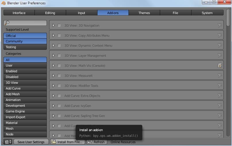
Navigate to your downloaded io_scene_mudrunner-master.zip file and install it.
Once installed, the new “Import-Export: DirectX Exporter for Spintires MudRunner” addon can be found in the “Supported Level: Testing” tab on the left. Put a checkmark in the box next to it to enable it, and then click “Save User Settings” at the bottom to keep it enabled for all future Blender sessions.
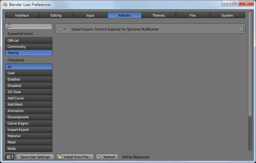
Use the Exporter
With the addon, export with File → Export → MudRunner (.x). The export dialog looks much like the original DirectX exporter, but with some new export options added and with some irrelevant export options removed. These options are explained more in the next section.
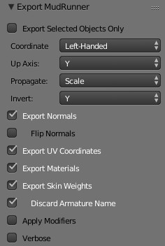
You can set a keyboard shortcut in Blender for the MudRunner Exporter. Right click File → Export → MudRunner (.x) in the menu and choose Add Shortcut. I like Ctrl-Shift-E as my shortcut. Be sure to save your User Preferences for future Blender sessions.
Recommended Exporter Settings
Most exporter settings should be left as the default value except where noted below. In most cases, the only option you need to worry about is “Propagate”.
The exporter inserts a virtual Root frame to transform the coordinate system and up axis from Blender’s system (right handed, Z up) to MudRunner’s system (left handed, Y up). With any Propagate option except “None”, these transforms are propagated at least one level of hierarchy, and the virtual Root frame is removed.
Export a Static Model for MudRunner
A static MudRunner model is the easiest type to export and multiple export options are possible. My recommendations are as follows.
To export a model, first set it up in the normal way in Blender with up pointing up (towards positive Z in Blender). Export it using my MudRunner exporter with the following options:
- [no check] “Export Selected Objects Only” (default).
- Coordinate System: “Left-Handed” (default).
- Up Axis: “Y” (default).
- Propagate: All. (Explained below.)
- Invert: (not relevant for static models).
With Propagate: “All”, the exporter pushes all transformations (translations, rotations, and scaling) from the hierarchical frames down to the mesh vertexes. This leaves no room for interpretation in MudRunner, so you always get exactly what you see in Blender.
You can also use the default Propagate: “Scale”. This pushes only scaling transformations to the mesh vertexes, leaving translations and rotations in the frame hierarchy. This is usually fine, but it only works with equal scaling in all directions. If any part of your model uses unequal scaling in the X, Y, and Z axes, the exporter averages these different scales to get a uniform scaling factor.
If your model includes no hierarchical scaling, you can also use Propagate: “None”. Be aware that with this option, the exporter leaves the Root transform frame in the .x file. This frame includes a negative scale factor to convert to MudRunner’s left-handed coordinate system. MudRunner can handle the negative scale factor for static models only; it fails for most dynamic models or other object types.
The remaining options are fairly straightforward and can generally be left in their default settings.
The Export Materials option is useful if you have a single mesh that requires multiple textures or other material properties. It is harmless to leave this option checked if a mesh has only a single material.
The Export Skin Weights option is useful only for dynamic models and plants. It is harmless for other objects.
Export a Dynamic Model for MudRunner
Setting up MudRunner constraints for a dynamic model is much easier if the frame coordinates and rotations are left in the hierarchy. I therefore recommend the following export options for dynamic models:
- Propagate: Scale (default).
- Invert: Y (default).
With Propagate: “Scale”, only the scaling factors are pushed through the hierarchy. Thus, MudRunner constraints can be set on a body using its frame location and rotation as set in Blender (i.e. the body frame’s local coordinate system).
There is a caveat to the phrase “local coordinate system as set in Blender”. No amount of rotation can make Blender’s right-handed coordinate axes line up with MudRunner’s left-handed axes without inverting at least one axis. By default, this is the Y axis (as viewed in Blender). You can choose to invert a different axis with the Invert option.
The images below show the effect of the Y axis inversion. The image for Blender is on the left, and MudRunner is on the right. Note that the model is not visually mirrored; only its internal coordinate system is inverted. I use this box model a lot for testing within MudRunner, so I’ve chosen to texture the box with its local orientation in MudRunner’s system rather than its original Blender orientation.
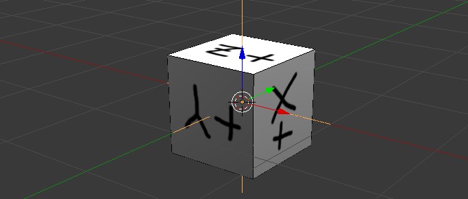
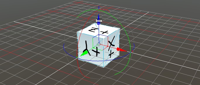
Since a negative scale is needed when exporting to MudRunner’s left-handed coordinate system, this scale factor must be propagated down to the mesh level. So even if you don’t use any scaling in your own hierarchy, you cannot use Propagate: “None” for a dynamic model.
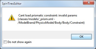
The remaining options can generally left in their default values.
The Export Materials option is useful if you have a single mesh that requires multiple textures or other material properties. It is harmless to leave this option checked if a mesh has only a single material.
The Export Skin Weights option is required if you use a deformable mesh. The Discard Armature Name option is also useful. See the “Model Deformation” section for details.
Export a Grass for MudRunner
MudRunner doesn’t support any hierarchical transforms for grasses, including the top-level ones used by the exporter to set up the coordinate system. Therefore, the following options are necessary when exporting a 3-D model to use as a MudRunner grass:
- Propagate: All.
- Invert: (not used with Propagate: All).
Export a Plant for MudRunner
MudRunner doesn’t support any hierarchical transforms for the single permitted visual mesh for plants, including the top-level ones used by the exporter to set up the coordinate system. However, it does support hierarchical transforms for the body frames used by the plant.
One option is to use Propagate: “All”, which causes all body frames to share their origins with the plant origin. You would then need PivotOffset for any body frames that require a different pivot point. You may also have trouble getting IsCapsuleCDT to work properly with this export setting since IsCapsuleCDT seems to expect the body frame to be modeled with a certain local orientation.
Alternatively, you can use Propagate: “Scale for body frames, else All”. This option requires that your plant’s visual mesh not be part of any body hierarchy (even the top-level body). This option behaves similar to Propagate: “Scale” in that it preserves the locations and orientations for all body frames, but it otherwise propagates all transformations to the plant’s visual mesh as required by MudRunner.
Credits:
Fuzball
Cannot get the idea why Spintires: MudRunner Mods are so special? Well then you have landed in the right place – we will explain everything that you probably want to know. So, let’s begin: Spintires: MudRunner Mods are additional files, which expand your options and provide you with new possibilities. Each Spintires: MudRunner Mod is designed to solve particular problems and help to boost your chances to overcome boundaries. If you cannot move forward and it seems that you’ve tried everything, Spintires: MudRunner Mod might offer you unseen features which will make you overcome all kinds of obstacles. This is the reason, why Spintires: MudRunner Mod free files are so popular all over the world – they assist a player and make everything solvable. If you find yourself in the situation where you have no escape, take a look at our suggested files and pick the needed upgrade. Completing Spintires: MudRunner Mod download is very simple and quick, so there won’t be any difficulties. If it sounds great, don’t wait a second anymore, this is a perfect chance to get the significant benefit against your competitors without spending much time or money. It’s about time to start playing smart and using all available choices. Don’t stay at the back of the line and surprise all your opponents. Become a leading player and accomplish goals that you even weren’t dreaming about. Sounds even too good? You will never know unless you experience it yourself. It’s definitely something worth trying – so go for it right now!
 (9 votes, average: 5.00 out of 5)

Do you happen to have a “Zipped” copy of this guide (w/graphics) for this editor?
It sure would be handy!